

Welcome to Jefa Rudder
We have rudder and bearings for your boat.
Who is Jefa Rudder?
Beginning in 1980, Jefa Rudder has supplied Rudder Bearings to over 40,000 boats. Jefa was founded by Jan Faurschou. Today Jefa Rudder is steered with the second generation at its helm, by Jan’s daughter Louise.

Did you know
Quality roller bearings.
All Jefa rudder bearings are produces with precision machined rollers and close tolerances to provide smooth operation under load. The close tolerance allows Jefa to eliminate the roller cage needed with sloppy bearings and keep the design simple for long term reliability.
Retrofit Bearings
Jefa Rudder produces replacement rudder balls for all old JP3 and Seaway (Bavaria, Elan, Salona, etc..) rudder bearing.
Jefa Rudder produces replacements for old Harken rudder bearings which is precisely match the original outer dimensions
Standard & self-aligning bearings
Jefa produces self-aligning bearings for rudder stocks engineered to flex. Self-aligning bearings also eliminate the need for precise alignment during installation. Standard or Non Self-aligning bearings are available at a lower cost and normally have a smaller outside diameter.
My Sailing Fix

Catalina Rudder Bearing Replacement
While anchored two seasons ago, I noticed a clunk when Priorities rocked back and forth from the wakes of passing boats. The sound clearly came from the rudderpost area in the lazarette. After visually observing the rudderpost wobbling back and forth with each clunk, I figured last winter was finally time to act on a project I had been putting off for a while: replacing the top rudder bearing.
Priorities is a 1996 Catalina 400 Mark I, and like many Catalinas around her size and vintage she has rudder bearings made from a hard plastic. They are a wear item, but should last a decade or two. One symptom of excessive wear is a bunch of play in the rudder that’s noticeable when shaking the bottom of the rudder after haulout. Rudder bearing wear is a gradual process, and isn’t a crisis when first noticed. However, I can see where it might aggravate wear on steering cables and autopilot drive linkages… also items on my winter project list. It also wasn’t going to get better with time, either.
Several years ago, I hired a professional to help me replace the bottom rudder bearing. Though the job itself wasn’t that complicated, it needed to be done while the boat was out of the water and high enough above the ground to allow us to completely remove the rudder from the boat. With a rudderpost that extends 3 feet above the rudder, we needed 3 feet of clearance under the bottom of the rudder in order to remove it. I worked with the boatyard to do the project while still in the slings after haulout, but before being placed on her cradle. An alternative is to dig a hole in the ground below the rudder… but that’s not that easy in frozen Wisconsin, or for those of us that store on concrete!
I had purchased the complete set of rudder bearings from Catalina Direct when I replaced the lower bearing. It was a whopping $620! Though I initially planned on replacing the top bearing the same year I replaced the bottom, the looseness seemed much better after replacing just the bottom bearing. I put off what I saw as unnecessary work until I started hearing that clunk two seasons ago.
After haulout last winter, a quick check revealed nearly an inch of play when shaking the bottom of the rudder. The bottom bearing itself had become loose from the hull, too, which was part of the problem. It did seem, however, that most of the motion was in the top of the rudderpost, confirming my observations earlier in the season. After our steering cable failure on our trip to Pentwater that same season, a steering overhaul was big on my list of winter projects… so I replaced the top rudder bearing this same winter.

I started this project by climbing into the bottom of the lazarette and getting photos of everything. Having photos of how systems look when fully assembled helps when reassembling them later… especially if i don’t finish until spring.
Since I planned a complete steering overhaul including cable replacement, I disconnected the steering cables from the quadrant, and removed the quadrant from the rudderpost. I also removed the autopilot tiller. When I replaced the lower bearing a few years ago, I delivered the boat to the boatyard a day before haulout before disconnecting the quadrant. Some other 400 owners have used their emergency tiller for the final maneuvers to the crane… but mine didn’t fit until recently.

Since I didn’t need to replace the lower bearing this time, I didn’t need to completely remove the rudder. Therefore, I did this project out of the water in the cradle, making logistics simpler.
Before any more disassembly, I compared the new top bearing with the old top bearing. The new top bearing is a self aligning bearing, involving a partial sphere sandwiched between two plastic rings. The self aligning feature allows the bearing to “wiggle” to stay aligned while not allowing lateral movement. Apparently it helps reduce friction when underway, when the rudderpost bends with stress. Unfortunately, its overall size is larger than the original on my boat.

With some careful measurements and fussing, I figured that simply mounting the top bearing on top of the bearing box wouldn’t work due to a lack of space. Some other Catalina 400 owners, especially owners of later models, might not have this issue since I’m willing to bet each boat’s bearing box is semi custom made and has slightly different dimensions. Some boats might even use this new self aligning bearing as an OEM part.
I came up with a design that should be pretty strong: the upper bearing straddles the bottom of the bearing box, transferring any lateral loads directly into the box. The bottom flange of the bearing mounts under the box, held up by a piece of G10 fiberglass and through bolts that also hold the top flange in place. To keep the spacing right, the top flange had a ¼” piece of G10 under it as well. I used ¼” G10 under the bottom flange, but in retrospect the bottom G10 piece probably should have been ⅜” or ½” for additional stiffness.

On my boat, the packing components around the rudderpost looked like they needed attention… large amounts of caulk had been put around a joint earlier in its life. Since a new packing assembly came with the bearing assembly, I decided I would replace it, too. This meant I needed to lower the rudder a foot to give me enough clearance above the rudderpost in the lazarette to swap old with new. Lowering the rudder this amount would also give me room to make minor modifications to the bearing box to accommodate my plan.
Filled with foam, I’ve heard the rudder isn’t that heavy when in water. On the hard, however, it’s pretty heavy, and felt like it weighed 100 pounds. It’s held up by one bolt above the top bearing. Since I was working alone, I built a stand of scrap 4×4 lumber to prop up the rudder a fraction of an inch and removed the top bolt.

After triple checking my measurements, I lowered the rudder down about a foot. I widened the hole in the existing bearing box to allow the upper bearing’s lower flange to fit better, and drilled holes for the through bolts. I installed the lower section of the packing assembly with screws, sealing the edges with 4200. Then I loosely fit all the remaining components that would end up under the bearing box around the rudderpost: the rest of the new packing assembly, the lower flange’s G10 brace, and the lower flange of the upper bearing. Then, I raised the rudder to full height again.

Getting the through bolts to line up took some work… I ended up drilling out the holes in the G10 pieces one size larger and used washers. The rudder is held up by a new stainless ring (supplied with the rudder bearings) atop the upper bearing. This ring needed to be drilled out as well to fit the new 5/16” bolt that matched the existing hole in the rudderpost.

Now that the new top bearing assembly fit correctly, I felt I could reinstall the loose bottom bearing again with adhesive. The bottom bearing is not self aligning, so I waited to glue this in place until after the top bearing was installed. Lowering the rudder one last time a few inches (or all the way out if replacing the whole thing), I removed the screws holding the bottom bearing in place, and pried the bearing out of the rudder tube with a crowbar and sharp knife.

The bottom bearing is mostly held in place with 3M 5200. Some call this the “devil’s glue,” since it forms a permanent bond that’s awful to remove from most substrates. However, the bearing is plastic, and not much bonds to plastic very well. On both occasions when I’ve removed the bottom bearing it wasn’t a disaster, especially since I could use a knife to cut through the bond. To facilitate future replacement, I used 5200 only on the bottom flange, NONE on the sides that go 2 ¼” into the rudder tube.
There are screws that hold the bottom bearing in place, too. With a hull thickness of 1 to 2 inches in this area, I used 1 ¼” long screws since the bearing flange is ½” thick. When I first replaced the bottom bearing I was told these screws are mostly there to hold the bearing in place while the 5200 sets. As a result, I didn’t tighten them much. At haulout last fall I noticed they had sheared off, possibly contributing to it coming loose again. This time around, I tightened the screws more firmly.
Raising the rudder one last time while the 5200 cured to ensure it cured in alignment, I installed the retainer ring and screw at the top bearing. A few days later I wiggled the rudder back and forth to check for any binding of the bearings. Without any steering connections, the rudder moved very easily, with only a slight resistance in one direction.
New ½” flax packing was installed in the new packing assembly, and the top compression ring tightened moderately to prevent leaks. This packing is above the waterline, so the boat won’t sink at the dock if this fails, but a seal is needed in waves and maybe when motoring.
To complete the project I reinstalled the quadrant and autopilot tiller. The bearing box cover was reinstalled and resealed with silicone caulk, and the emergency tiller access port got a new O-ring purchased from McMaster-Carr .
After a season of use, including several instances of being stressed when sailing overpowered, and sailing in 6-8 foot waves, everything seems to be holding up well. Hopefully, the new bearings will last many more years. If or when they need replacement again, though, it should be easier… assuming the bearing design doesn’t change again!

Share this:
- Click to share on Twitter (Opens in new window)
- Click to share on Facebook (Opens in new window)
4 thoughts on “Catalina Rudder Bearing Replacement”
Do you spend time on the Catalina 400 Facebook page? Oh jeez, I practically live there! Sailing on hull 323, a 400 mkii and am planning a rudder bearings replacement upgrade soon/next haulout/Oct or sooner. Digging into this post as I spend time in the lazerattes and atop the aft bed with the ceiling molding pulled. If you don’t mind I’ll be sending a short video of my mid-bearing or mid-housing (remember, I’m just wrapping my head around the parts and nomenclature). More soon. Thanks. Instagram for us is beyond.the.bnb if you are curious. Cheers!
Hey Curt! Remember your MKII will likely have a significantly different steering system… probably a radial drive wheel rather than a quadrant like on my MKI. I think the bearings will work similar, though.
Great article. Any tips on how you removed the rudder bearing box cover? I removed the sealant in the gap around the cover but cannot lift or pry it out.
From what I remember, all I had to do to remove the cover was remove the sealant and unscrew the cover. There may be an extra layer of 4200 hiding deeper in the joint, so you might need a long blade or scraper to cut it.
Leave a Reply Cancel reply
- WellFound Yachts
- 80 Hatteras Motor Yacht 2014
- 70 Johnson Flybridge Motor Yacht 2003
- 62 Offshore 2006
- 58 Viking 1997
- 54 Hatteras Sport Fisherman 2006
- 1987 Deerfoot 74
- 1985 Custom Pedrick 61Cutter
- 1999 Berkstresser 60 Performance Catamaran
- 2015 Gunboat 60
- 2003 AMEL 53 Super Maramu
- 1972 Hinckley 53
- 1990 Passport 50
- 50 Jeanneau 2015
- 2009 48′ Island Packet 485 Cruising Cutter
- 2008 Outbound 46 Sailing Yacht
- 43 Fountaine Pajot Belize 2000
- 39′ Robertson and Caine Leopard 2012
- Buying your boat:
- WellFound Weather Map
- Tide Predictions
- Wind and Waves Predictions
- Coastal Winds
- Offshore Weather Planning
- WellFound News
- WellFound Boating Tips
- Articles of Interest
Replacing the rudder bearings on a 39 foot Catamaran
- Pets on board ( Dog gone!!!)
- WellFound Yachts Deliveries
- Delivery of 52 Sailing Yacht from St Maarten to Italy 2011
- Delivery of ‘Gone With The Wind II’ from Florida to Panama February 2012
- Delivery of ‘Second Chance’ from Florida to Connecticut June 2008
- Early April Delivery North Bound. 2015
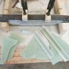
Original Tube
This bearing and housing is really very ingenious. Unlike other shaft bearings this bearing can twist and turn within the housing, allowing for movement of the rudder shaft. BUT: 1- It is hard to get anything to stick to aluminum. 2- A round peg in a round hole does not have a lot of resistance to a twisting motion. 3- Aluminum in close proximity to stainless steel that is immersed in salt water is prone to galvanic action.
The bearing housing was not held solidly in place and when the aluminum started to corrode, the bearing stopped turning in its housing. As the rudder shaft started to corrode, more friction was put on the bearing until the aluminum housing started to turn in the fiberglass hull, allowing water to enter between the aluminum housing and the hull. Replacing the old bearings with the same product was not an acceptable option. We purchased two more typical bearings and fiberglass tubes. We enlarged the wholes that the old bearings went through and then fiber glassed the new tubes firmly in place, being careful to keep the new tubes inline with the original upper bearings that were attached to the deck.
After a few weeks and a few hundred miles of sailing we could see that this new system worked perfectly. With it there is little to no friction, no ingress of water, and as there are no dissimilar metals, there can be no galvanic action. This new system should last as long as the boat herself, with little to no maintenance.
Featured Yachts
- PSS Shaft Seal
- Fendertex® Fenders
- Revolve Boat Hook
- Jefa Rudder & Rudder Bearings
- Jefa Autopilot Drives
- Jefa Steering
- Lecomble & Schmitt Autopilot Drives
- Lecomble & Schmitt Hydraulic Steering
- R&D Marine
- Crystal Prop
- Floor Anchor
- Clamp Jacket
- Shaft Retention Collar
- Machine Shop
- Max-Prop Reconditioning
- Testimonials
- Schedule Virtual Meeting
- Company Info
- Boat Show Calendar
- Roller Bearings
- Retrofit & Replacement Bearings
- Standard & Self Aligning
- Rudder Stocks & Rudders
- Bearing Maintenance

Rudder Stocks

Rudder Blades

Rudder Bearings

Sealing Systems

Tiller Heads

Deck Covers

Jefa Rudder Bearing Maintenance
Don't forget to maintain your rudder bearings. If you have concerns take care of it now. Preventive maintenance of your Rudder Bearings is always a bargain when compared to unplanned repairs or an emergency resulting from neglect. All repairs and maintenance must be done by qualified professionals
Make a note of how the steering feels when your boat or your rudder bearings are new, or when you have just launched. Use this information for comparison if you have any work done on the steering or rudder bearings in the future.
Shortly before you haul your boat for any service, assess if there is any change in the steering or bearings and share this information with the boat yard. Inspect the steering and bearings annually and at each haul out.
Things To Check
Here are some of the common things to check if you hear or feel something unusual and believe it may be the rudder bearings.
Marine growth can be fouling the bearings.
This is most common in the lower bearing. This will have to be cleaned out. You may need to remove the rudder for this. Flushing the bearing when possible and at least annually can help avoid this.
Antifoulling paint near, on, or inside the bearing.
The wrong paint on an aluminum housing will damage it. If this happens you must replace the corroded parts. Keep copper-based paint at least 2" away from any aluminum bearing parts. The aluminum bearing housing must be prepared, primed and painted with products intended for aluminum below the water load.
High loads in one direction for a long period of time.
If you are on the same tack for days at a time you will displace the grease to the unloaded side of the bearing. The bearing will squeak until it is loaded in the other direction.
The rudder may be touching the hull.
All boats bend and twist when they are sailing. When this happens the bearing never get closer, the bearing can move further apart. If the bearings move apart the rudder may be rubbing against the hull. Have the boat yard lower the rudder slightly in relation to the upper bearing and check if the noise, vibration or squeak is gone.
A Note About Grease -
Only lubricate your rudder bearing if and where the manufacturer recommends. The rollers in a Jefa Rudder Bearing should never be greased. Self-aligning Jefa Bearings do require synthetic grease between the self-aligning sphere and the bearing housings. O-rings should also be lightly greased.
Rudder Shaft
The rudder shaft should be inspected once a year for signs of electrolysis. Circular patterns of corrosion on the shaft surface are a good sign of this. When the rudder blade has a tight fit to the hull, look at the gap. Normally it's not necessary to drop the rudder for further inspection, unless the rudder system has developed backlash or if the shaft rotates irregularly. If you have any concern for electrolysis, please read Jefa's electrolysis page carefully.
Important tips and guidelines on how to use antifouling on the rudder blade and rudder shaft can be found in Jefa's antifouling instruction document .
Another area for attention on the rudder shaft is the locking of the tiller arm or quadrant on the shaft. Carefully inspect to see if there's movement between the parts. Any movement could wear out the keyway in the shaft which can lead to costly repairs.
Bottom Bearing
The bottom bearing doesn't usually need any maintenance except for rinsing with water when the ship is hauled out. The main reason for this is to remove the salt water out of the bearing housing so it can't crystallize. If the shaft rotates irregularly, it can cause some rollers to develop a flat spot. This will have been caused by a temporarily blocking of the rollers by dirt parts. In most cases this will have been caused by dirt falling in from above on open tube systems. Use a gaiter to prevent this in the future. PYI Inc. can make you a Jefa Gaiter, please contact us for more details.
The removal of the rollers is quite simple: Drop the rudder out of the ship. Remove the thin delrin ring holding the roller track. Now the rollers and roller track will fall out. Mount the new rollers. To ease this job one can use a balloon to keep the rollers in place (NEVER use any grease). Mount the bottom roller track again and clip-in the newly supplied delrin ring. Watch the YouTube video below for instructions.

When you are experiencing a stiffer rudder and steering feel than normal, it could be caused by a corrosion or lime problem in the bearing. Please read this service tip for more info.
If lip seals are used to seal your rudder system, please carefully inspect them for signs of cracks. If the seals show signs of cracks in the surfaces, immediately replace them with our new type PUR seal. These seals have no steel components inside anymore and will last much longer. It's advisable to spray a small film of teflon spray on the lip surface for better operation on the shaft. Manuals for replacing lip seals can be found here . It's advisable to inspect PUR seals once a year for defects.
Gaiters should be inspected every year for mechanical damage. Carefully inspect the gaiter for any signs of cracks, especially around the hose clamps. If you don't trust the sealing capabilities of the gaiter any more, replace it with a new one. Gaiters can be supplied in unglued state, so the rudder shaft doesn't have to be dropped. Wrap the new gaiter around the rudder stock, apply the specially supplied neoprene glue on the indicated area. Carefully press the surfaces together and let it dry for a while. Secure with the hose clamps again. For details about the appropriate dimensions, see the installation section .
Top Bearing
The top bearing doesn't usually require any maintenance. Only if your yacht is located on a sandy environment and the bearing is exposed (no deck cover present), you should rinse the bearing to wash away any sand and dust between the rollers and the housing. This should be done every year.
Vertical Locking
The vertical locking mechanism should be inspected yearly for any signs of movement relative to the shaft. Its advisable to loosen the set screws one after each other to be re-greased. This will make sure the vertical locking can be removed in the future for the possible removal of the rudder stock. For details about the proper mounting procedures, see the installation section .
If the vertical locking is achieved by a locking ring or tiller head on a delrin ring, you could experience a squeaking noise. This can be prevented by spraying a some teflon on the delrin ring.
- Breaking News
- 2011 Results
- 2012 Results
- 2013 Results
- 2014 Results
- Specifications
Rudder Bearing Replacement
- Asymmetrical Prod
- Owner’s Pages
Happy Puppy was delivered with the factory standard bearings which really aren’t bearings at all, but rather spherical polyethylene bushings. The lower bushing is mounted in a short fibreglass tube bonded to the bottom of the boat, while the upper unit is mounted to the underside of the deck using a rather Rube Goldberg-ish fibreglass housing that is bolted to the deck with four 5/16 carriage bolts. As you can see from the photo, it is a rather ugly arrangement as can be seen from the photo, but its appearance pales in comparison to how it feels. In a word – dead. Very little feedback to the helmsman because of all the friction, and frightening lag in response in fresh downwind conditions, not to mention the fearsome groaning under load. While we had lived with it for the first two seasons, we decided in the winter of 2009 that enough was enough and that it was time to put in a proper steering system.
Factory Rudder Install
The above photo shows the factory rudder install, aka the ugly duckling. The upper spherical bearing can be seen poking out of the heavy fibreglass mount on the underside of the deck, while the lower unit is installed in the fibreglass tube hidden under the black rubber gaiter. The upper unit is held in place with four machine screws, one of which can be seen near the center of the fibreglass mount. What you can’t see from the photo is that carbon shaft is fitted with two stainless sleeves, one for the upper bushing, and another for the lower. The quadrant is mounted to the shaft using a 5/16 inch bolt, which is drilled through the upper sleeve and shaft.
From the forums of the class website, we discovered that at least one boat had been upgraded with Jefa bearings and that the owners seemed really pleased with the results. So we followed the path through Jefa to their Canadian representatives, CCI of Ottawa where Dave Bradley took great care of us. We settled on the gold-plated version, with self-aligning needle bearings top and bottom, and double thrust bearings in a nice-looking replacement upper housing. The two versions can be found on the Jefa ftp server : The new bearings are beautiful!
So in the spring of 2010, we removed the rudder to begin the task of replacing the bearings. Removal of the quadrant was quick and easy, but upon removing the gaiter on the bottom bearing tube, we were shocked to find that the bottom bushing was filled with stainless drill chips that had apparently come from the drilling of the hole in the shaft for the rudder quadrant. These were nicely embedded in the bushings and had scored them pretty badly. Strike one for quality control!
Once the steering gear had been disassembled, the shaft dropped out easily, and we could do a proper inspection of the work area and the rudder post. The first step was to remove the upper bushing housing and cover plate. The bushing was fitted in a rather massive fibreglass lump (not a very technical term, but certainly accurate!). Fortunately, once the 5/16 inch bolts holding this in place had been removed, this unit came away easily with a few whacks on a chisel inserted into the joint between it and the deck. Score one for weight savings.
The new cover plate and upper bearing housing were quite a bit larger in diameter, so we had to cut out the hole in the deck to accommodate the new bearing unit, then test fit it and drilled the mounting holes. The mounting hole circle lies very close to the bearing housing diameter, so care was required to ensure that the through hole was cut accurately. But once done, the bearing housing slipped in easily, and needed only to be bolted in place with six 1/4 inch machine screws and of course the requisite sealant. We dry mounted the unit to test the fit, waiting until the entire system had been installed to finalize the mounting.
Turning to the bottom end of the shaft, CCI/Jefa had supplied the lower bearing mounted in a neat fibreglass tube that would fit cleanly inside of the existing tube. A test fit quickly revealed that there was some interference, but some diligent work with a drum sander got the two to mate very well in short order. The rudder shaft was test fitted to determine the correct height for the lower bearing unit to keep the rudder top gap to a minimum. Only one problem – the rudder shaft did not fit inside the bearings!! Good thing that we had not bonded anything in place yet!
So out came the two bearings, and the rudder was laid on the ground to figure out what was up. checking the shaft with calipers, we discovered that the shaft was oversize and significantly out of round. Discussions with the good folks at CCI revealed an easy solution for the size problem – replacement of the needle bearings with custom bearings to fit, and new units were ordered from Denmark. Unfortunately, erupting volcanos in Iceland had grounded air traffic, so after a two week delay, we had the requisite new bearings in hand, and we could start anew.
Resolving the out of round was straightforward, but tedious, involving carefully lapping the shaft with a diamond file. Fortunately Bill Layton of the Quebec Evolution loft was on hand to guide the process and keep me honest, and after a few hours of work we had the shaft nice and round and the bearings fit beautifully. A suggestion to anyone else contemplating this upgrade: carefully measure your shaft diameter in as many places as you can before you order the unit, and provide the exact actual dimensions when ordering the bearings. The difference was small (in the order of 0.4mm) but that was enough. The bearings are very precise, and need to be to ensure that there is no slop in the shaft mounting. Also, make sure that you fix any out of round before you finalize the measurement. We did not do this, and are left with about 1/4 inch of play at the bottom of the rudder. If and when we ever replace the needle bearings, we will resolve this, but it is not enough to worry about in the meantime. Much of the out of round was in the region of the quadrant mounting bolt hole – one can only assume that the drilling of this hole was the cause.
With the above photo, the two sleeves are clearly visible. Also visible is the unsleeved upper portion of the shaft that ultimately caused us to re-think the upper bearing mounting (more below)
With the rudder now ready and fitting to the bearings, we epoxied the bottom unit in place and let it cure. We then inserted the rudder and lined it up vertically before finalizing the mounting of the upper unit. The quadrant was then re-installed, and the replacement was complete – or at least it should have been. Unfortunately the upper sleeve on the shaft was located too low to fully engage with the upper bearing which was obviously non-ideal. Further discussions with Jefa/CCI led us to leave it at that for the season, after being assured that the bearing was over-designed and that the incomplete contact would not be a problem in the short term.
The change in steering was phenomenal. The helm was much lighter and responsive, the feedback was great, even in light winds, and the backlash and groaning under heavy loads was completely gone. it was like a new boat.
During the winter of 2010 we worked with Jefa/CCI to resolve the bearing fit. Ultimately, we decided to mount the upper bearing underneath the deck instead of on the upper deck surface. We designed and had built by Pure Ingenuity in Kingston a new cover plate and ring that matched the upper bearing unit. A drawing is below for those interested. The only real challenge in this was that by moving the bearing housing downwards, we also had to move it aft slightly to account for the inclination of the shaft. To ensure adequate strength, we cut a ring of G10 and mounted it to the under surface of the deck, then using a well waxed wooden plug, filled the resulting gap to get the hole size just matching the bearing housing. The photos show the plug in place, the resulting fill and the new holes. The rudder was re-assembled in the spring of 2011, and the bearings now lined up perfectly with the shaft sleeve. The photos of the completed install show how neatly everything has come together. We are very very pleased with the results, and are fully confident in the new system.
The shift in location of the bearing for under-deck is visible in this photo. The gap was filled with epoxy with glass filler, and reinforced with a G-10 plate underdeck (below).
The next series of photos shows the bearing installed, then with the shaft (note how the bearing sits fully on the sleeve now) and the cover plate in place. Just like it was meant to be!
Finally, the complete install. Much cleaner!
In this last image, the set screws holding the shaft are visible on the lower part of the upper bearing unit. These mount to the thrust bearing.
I would be happy to share my experiences with anyone interested in the same upgrade. Just drop me a line using the contact link
Jefa drawings Adaptor plate drawings (for under deck mounting of upper bearing unit)
CCI Composites Collins Bay Yacht Club C&C Yachts Evolution Sails Geoff Webster Photography bird.ca Pride Marine
Designed by Elegant Themes | Powered by Wordpress
Professional BoatBuilder Magazine
The rudimentaries of rudders.
By Steve D'Antonio , Jul 12, 2018

Even stoutly constructed rudders are vulnerable to deterioration over time, especially when mild steel or high-carbon-stainless steel is buried in composite foil sections, which inevitably become saturated with seawater.
Like other systems and gear aboard cruising and commercial vessels, rudders have terms to identify their parts and functions. When measuring a rudder, the span and chord are the vertical height and fore-and-aft width, respectively, while the top of portion closest to the hull is referred to as the root , and the bottom is called the tip . Another term frequently used when discussing rudder design, particularly for sailing vessels, is aspect ratio —simply the square of the rudder’s span divided by the rudder’s area. As a rule of thumb, longer, narrower rudders are more efficient than short, wide rudders, and the aspect ratio describes precisely this relationship. Thus, rudders on high-performance sailing vessels are said to have a high-aspect ratio. Walking around a boatyard one day and measuring a few cruising sailboat rudders, I came up with aspect ratios of between 1.7 and 2.1, while one high-performance sailing vessel’s rudder came in at 3.5. The 20-knot semi-displacement lobster yacht’s rudder I measured yielded an even 2.0 aspect ratio, which is considered respectable for this application.
More identifiable rudder components include the stock ; web or armature ; rudderport or log ; stuffing box or compression tube ; bearing ; gudgeon ; and pintle . Not every rudder has all these components.
Rudderstocks
The rudderstock is essentially a shaft or tube that protrudes from the top and sometimes the bottom, depending upon type, of many rudder designs. Because this component provides the primary connection between the rudder’s blade (the flat section that imparts the steering force) and the vessel’s steering system, its design, construction, and material are consequential.
Most stocks are made of stainless steel, bronze, or aluminum, while some are carbon fiber, and they may be solid or hollow. Stainless steel is by far the most common, but it has a penchant for crevice corrosion when exposed to oxygen-depleted water. Insidiously, corrosion nearly always occurs in places where it cannot easily be seen—such as inside many composite (fiberglass and core material) rudder blades and beneath flax-type stuffing-box packing (the problem is exacerbated when the vessel is used infrequently).
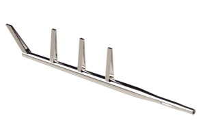
This all-stainless rudderstock and webbing is well crafted and ready to be covered with its composite shell.
Of the stainless steel alloys, some resist this corrosion better than others. Stainless-steel rudderstocks should be manufactured with strong, highly corrosion-resistant proprietary shafting alloys such as A22. The next best choice is 316L stainless steel, which also resists crevice corrosion well. Critically important is the L suffix, meaning “low carbon,” a requirement if it is to be welded, as nearly every rudderstock must be, to the support within composite rudders, or to all-metallic plate-steel rudders. Failure to source low-carbon stainless steel for the stock or the web leads to weld decay, sometimes referred to as carbide precipitation, where the region around the weld loses its resistance to corrosion and rusts when exposed to water.
Aluminum rudderstocks are nearly always tubular. Common on aluminum vessels to reduce the likelihood of galvanic corrosion, aluminum stocks are also relatively common on fiber reinforced plastic (FRP) vessels, particularly large ones. Rudder blades, particularly on aluminum vessels, are often fabricated from aluminum. Of the various aluminum alloys, only a few possess the necessary corrosion-resistance and strength necessary for use as rudderstocks. Of these, the 6000 series, and 6082 in particular—an alloy of aluminum, manganese, and silicon—are popular for this application.
Because aluminum, like stainless steel, suffers from corrosion, it should not be used as stock or web material in composite rudders. Referred to as poultice corrosion, it occurs when aluminum is exposed to oxygen-depleted water. Because oxygen is what allows aluminum to form its tough, corrosion-resistant oxide coating, the metal should never be allowed to remain wet and starved of air as it would be inside a composite rudder blade after water makes its way in around the stock and pintle.
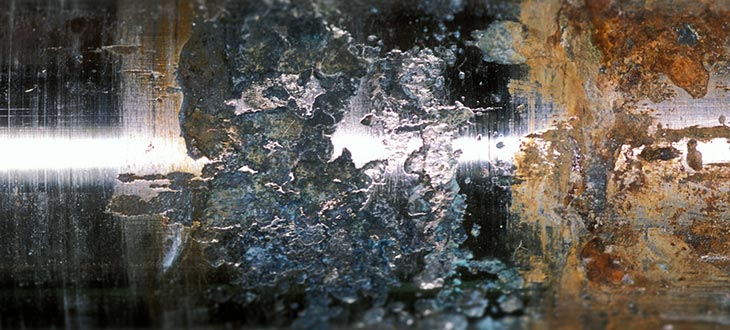
Rudderstock material can corrode in way of the oxygen-starved environment around the packing in a stuffing box.
Bronze, a once popular rudderstock material, is no longer common in today’s production vessels. Although strong and exceptionally corrosion resistant (immune to crevice corrosion), bronze is not easily welded to attach to a rudder’s internal structural webbing, and has thus been supplanted by stainless alloys. Bronze rudderstocks, particularly those that have seen many sea miles, are also known for wearing, or hourglassing, within stuffing boxes, where the flax rides against the stock. If a bronze stock rudder is chronically leaky, disassemble the stuffing box and check for excessive wear. The same is true for stainless and aluminum stocks: chronic leakage is often an indication of corrosion at the packing. Finally, because of their galvanic incompatibility, neither bronze nor copper alloys should be used aboard aluminum vessels for rudderstocks or any other rudder or stuffing box components.
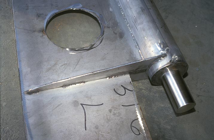
Mild-steel webbing welded to a stainless-steel rudderstock is a recipe for eventual corrosion and failure.
The webbing, or internal metallic support system, in most composite rudders must be strong enough to carry the loads of service and be made of the appropriate material. At one time, many rudders were built using stainless-steel stocks and ordinary, rust-prone mild or carbon-steel webbing. Inadvisably, some still are. The union between a stainless stock and FRP rudder blade is tenuous at best (the two materials expand and contract at different rates) and stainless steel’s slippery surface makes adhesion to the laminate resin a short-lived affair. Once water enters the gap between these two materials, it will reach the webbing and associated welds. Thus, all the materials within this structure must be as corrosion- and water-resistant as possible, and the core material must be closed-cell—often foam—and nonhygroscopic.
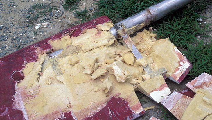
This destroyed foam-core and stainless-steel rudder reveals the conventional construction of such appendages.
Additionally, where possible, the stock should consist of a single section of solid or tubular material; i.e., it should not be sleeved, reduced, or otherwise modified or welded unless done so in an exceptionally robust manner. The webbing must be welded to the stock, but the structure of the stock should not rely on a weld that would experience cyclical, torsional loading.
The webbing in the form of a plate or grid should be welded to the stock with ample horizontal gussets (small wedges welded where the stock and webbing interface), which will reinforce welds 90° to the primary web attachment.
Whether the rudder is spade (supported only at the top) or skeg hung (supported at the top and the bottom), the stock must pass through and be supported by the hull. This is usually accomplished by a component known as a rudder log, or port. In its simplest form it’s a tube or pipe through which the stock passes. Nearly all logs incorporate two other components—a bearing and a stuffing box. The bearing may be as simple as a bronze or nonmetallic bushing or tube inside of which the stock turns; or it may be as complex as a self-aligning roller-bearing carrier that absorbs rudder deflection and prevents binding.
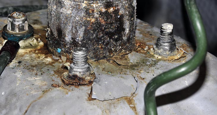
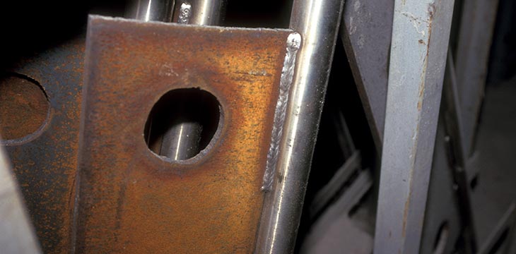
This rudder log is leaking, corroded, and poorly supported, with washers compressing into the backing plate and gelcoat cracking off.
The log transfers tremendous loads and must be exceptionally strong and well bonded to the hull. Fiberglass vessels should rely on a well-tabbed-in purpose-made tube (its filaments are wound and crisscrossed and thus quite strong) that is supported with a series of vertical gussets that distribute the load to the hull’s surrounding structure. On some spade rudder installations, particularly where the log is not, or could not, be long enough, an additional bearing is used at the top of the stock, above the quadrant, where it is supported by the vessel’s deck.
On metal boats the design is similar but with a metal tube welded in place, supported by substantial gussets. For vessels with skeg-hung rudders, the strength of the rudder log is still important. However, because the loads are not imparted by a cantilevered structure, logs used in these applications may be less substantially supported.
Stuffing Box
Unless the rudder log’s upper terminus is well above the waterline or on the weather deck, it is typically equipped with a stuffing box similar to those used for propeller shafts. But unlike a shaft stuffing box, the rudder’s stuffing box shouldn’t leak much, if any, seawater. Because the rudder turns slowly, friction and heat are not a problem. Packing (i.e., waxed-flax packing like that in traditional stuffing boxes) can typically be tight enough to stem all leakage, and lubricating it with heavy water-resistant grease will reduce friction and leakage.
Stuffing boxes that are above the waterline while the vessel is at rest, such as those on many sailboats, are often the most chronically leaky, because the packing tends to dry out and contract. To avoid this, liberally apply grease to the packing material itself; this requires partial disassembly of the stuffing box. Alternatively, a galvanically compatible (316 stainless or Monel for bronze stuffing boxes) grease fitting may be installed and periodically pumped with grease to keep the packing lubricated.
Rudder Bearings

Well-engineered rudder bearings support and lubricate the rudderstock.
Rudder bearings range from the basic rudderstock turning inside a bronze log, to the sophisticated aluminum, stainless, or nonmetallic roller bearings installed in a self-aligning carrier. For most cruising vessels, the choice of bearing is not as important as knowing which type of bearing is in use and its strengths, weaknesses, and maintenance needs. The simple shaft that turns inside a bronze log is durable and reliable but more friction-prone than roller bearings. If lubrication access or a grease fitting is available, it should be pumped with grease periodically, although most rudders rely solely on seawater for lubrication, which is perfectly acceptable.
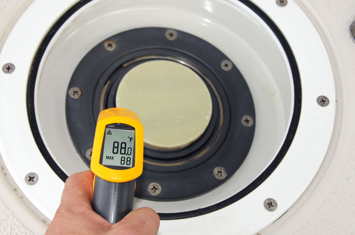
This synthetic upper bearing worked fine in cool temperatures, but when it heated up in the sun, the material expanded and caused binding in system.
Nonmetallic sleeve and roller bearings, often made of ultra high molecular weight polyethylene (UHMWPE), require no maintenance, are extremely slippery, and will not absorb water, an essential attribute for nonmetallic bearings. Delrin and nylon, for instance, will absorb water, expand, and lead to rudder binding. On several high-performance sailing vessels, I’ve had to replace nylon or similar bearings with UHMWPE to restore the steering to its proper specification and effort level.
Propeller Removal
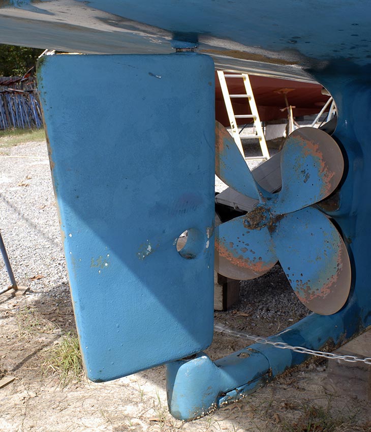
Shaft removal should be possible with the rudder in place. This conventional skeg-hung rudder has a hole to facilitate shaft removal when the rudder is swung hard to port or starboard.
Whether a rudder is a spade or skeg-hung design, it’s important to determine how it will affect the removal of the propeller or the propeller shaft. Is there enough clearance between the shaft’s trailing end and the leading edge of the rudder to allow the propeller to be removed or to use a propeller removal tool? Can the shaft be slid out without removing the rudder? Some rudders are equipped with shaft-removal holes, while others are installed slightly offset from the centerline; or the rudder’s leading edge has an indentation to allow the shaft to be removed. The propeller should be removable without having to unship the rudder. The dimensional rule of thumb calls for clearance of at least the prop’s hub length between the aft end of the shaft and the leading edge of the rudder.
Rudder Stops
The rudder’s movement should be unimpeded as it swings approximately 35° in either direction, making no contact with hull or propeller. Just as important as the rudder travel is how its movement is checked. Other than for the smallest runabouts with jacketed cables, all inboard rudders should rely on hydraulic cylinders to check rudder travel (provided they are designed to do so, and most are) or be equipped with robust stops. Stops must be integral to the hull, supported by substantial tabbing or a welded and through-bolted structure for fiberglass vessels, or by welded angle and shelves for metallic hulls.
About the Author: For many years a full-service yard manager, Steve now works with boatbuilders and owners and others in the industry as Steve D’Antonio Marine Consulting. He is an ABYC-certified Master Technician, and sits on that organization’s Hull and Piping Project Technical Committee. He’s also the technical editor of Professional BoatBuilder .
Read more Repair articles
Quick Custom Molds
Making one-off composite parts in the shop.
Repairing Bent Props with TrueProp Software
With all the advances in automation and electrification of boat propulsion systems, propellers remain critical to the task of converting power into propulsion. Made of bronze, nickel, aluminum, stainless steel,… Read more »

VacPuc Checks Your Vacuum Bags
It’s possible to monitor houses, cars, cats, and boats by smartphone, so why not check vacuum bags during resin infusion? Now composite technicians have this option with VacPuc, a new… Read more »

Recent Posts
- Find out how 3D printing can help your boatbuilding with MASSIVIT
- Van der Werff’s Curved Wood
- Departures: Carl Chamberlin
- SAFE Boats Regains Small-Business Status with Employee Ownership
- SNAME Powerboat Symposium Is Back
- Companies (85)
- Construction (106)
- Design (161)
- Drawing Board (10)
- Education (25)
- Environment (16)
- Events (21)
- Materials (50)
- Obituary (18)
- People/Profiles (49)
- Products (16)
- Propulsion Systems (32)
- Racing (16)
- Repair (37)
- Rovings (317)
- Short Cuts (3)
- Sponsored Partner News (14)
- Systems (80)
- Task Sheet (1)
- Uncategorized (26)
- Wood to Glass (7)
ProBoat.com Archives
- Practical Boat Owner
- Digital edition

How to build a rudder for your boat
- August 30, 2023
Hitting a submerged object destroyed Mike Gudmunsen’s rudder...so he set about making a new one

The rudder horn on Mike Gudmunsen's yacht had parted company from the palm, leaving the two sides of the palm still bolted to the hull. Credit: Mike Gudmunsen Credit: Mike Gudmunsen
How to build a rudder
The Blackwater estuary above Osea island dries at low water, writes Mike Gudmunsen .
Over the years, wooden jetties, fish traps and even barges have been left to decay at the margins, presenting hazards for the unwary – along with more recent man-made obstacles such as the causeways to Osea and Northey islands.
The spring tides were pretty big and the river had swelled, covering the surrounding salt mashes. Northey island had all but disappeared, apart from the hillock upon which the farm building sits.
I’d enjoyed a good sail around Osea island in my Pegasus and had time for a brew in Goldhanger Creek, but on leaving I became disorientated due to the unusually large expanse of water.
I strayed into an unfamiliar inlet and this was my undoing, as no sooner was I in than I was aground.
Frantic engine manoeuvres and rocking the boat on its keels released the boat, then as I proceeded back towards the main channel there was a resounding crash, the boat stopped dead and the tiller was wrenched from my grasp – I’d hit a submerged object and, whatever it was, it was pretty hard.

Although Mike had previously reinforced the hull around the rudder connection, the grounding still did damage. Credit: Mike Gudmunsen
From the tiller angle and the visible damage to the transom top in way of the upper rudder bearing, something was very wrong.
With minimal steerage, we limped back to our mooring further upriver to contemplate what to do next.
When we hauled the yacht out and inspected the damage, we found the rudder horn had parted company from the palm, leaving the two sides of the palm still bolted to the boat hull .
I’d reinforced the hull around this connection back in 2009 as I was concerned about the potential effects following an impact on the rudder – fortuitously, as it turned out.
Without this additional reinforcement, I suspect the bolts would have been pulled through the GRP and I could have been looking at a total loss.

The remains of the palm. Credit: Mike Gudmunsen
Pegasus yachts have a rather unusual rudder arrangement.
A cast aluminium rudder horn, which forms the leading edge of the rudder for about half its depth, is bolted via a palm to the hull.
At its lower end, a pintle bearing supports the rudder and takes most of the lateral rudder force.
A hollow stainless steel shaft passes through the pintle bearing and terminates above the transom at the tiller head.
Having removed the rudder and unbolted the remaining bits of the palm, I toured various boatyards and marinas hoping to get the rudder repaired.
The builders of Pegasus yachts went out of business many years ago, and it was evident that a replacement cast rudder horn was as rare as hen’s teeth.
So, the only option was to design and fit a spade rudder and move away from the original ‘mariner’-style rudder arrangement.
Designing a new rudder
The helm has always been light and responsive, so I was anxious to maintain those qualities in the new rudder.
I kept the original rudder dimensions and aspect ratio and also the rudder stock position relative to the leading edge.
The original rudder had a chord of 410mm and a maximum thickness of 63mm.
A NACA 0015 aerofoil is very close to these requirements, and I was able to get the section offsets from a site on the internet.
There are important differences between the original ‘mariner’ rudder and the proposed spade rudder .

A cast aluminium rudder horn, which forms the leading edge of the rudder for about half its depth, is bolted via a palm to the hull. Credit: Mike Gudmunsen
The original carried the rudder lateral force via the pintle bearing and into the rudder horn which resists bending at the bolted connection to the hull.
With this arrangement, the rudder stock essentially only carries the rudder torque and, as a consequence, the shaft can be hollow and of modest diameter.
Mine was 38mm diameter with a 3mm wall thickness.
For a spade rudder, the stock itself has to resist bending, shear and torsion, and would clearly need to be a lot thicker and possibly solid.
Calculating the loads on the rudder
A quick trawl on the internet will give numerous references to methods to calculate the forces on a rudder.
They basically all use the blade area (Ar) and the boat speed (V) in knots, together with a few other parameters such as lift coefficient, blade aspect ratio and so on.
For my chosen aerofoil section, I took the design lateral force (Dlf) on the rudder blade, measured in Newtons, to be:
Dlf =100A(V+3)2
The eagle-eyed will notice that lift coefficient and aspect ratio don’t figure in this equation as my 3-knot augmentation of the speed may be considered to compensate for these effects.
The original rudder was 980mm high with a chord of 410mm, giving an area of 0.4018m2.
I took the design speed of my 26ft yacht to be 5 knots. Hence, the lateral force came out to be 2,572N (262kg).
This force acts at the vertical centre of the blade area and, for the NACA section I had selected, at 1⁄3 of the chord from the leading edge.
Continues below…
Do you know your rudders?
Do you know rudders? Boatyards are a great place to get to know different types of keels, rudders and other…
Adding a rudder to a small outboard
Jim Miller suggests a neat way to add a rudder to a Honda BF2.3 outboard motor to aid steering at…

How do you close the gap between the rudder and propeller?
Practical Boat Owner reader David Blackborow is trying to find out the best way to close the gap between the…

Orcas left us rudderless! Yacht couple tell of terrifying ordeal off Spain
Zoe Barlow shares her experience of losing a rudder during sustained attacks by orcas whilst sailing her Sun Odyssey 40…
Having decided on the location of the upper and lower bearings, a simple moment calculation about the top bearing gave the reaction force at the lower bearing (3,983N): likewise, taking moments about the lower bearing gave the reaction force at the upper bearing (1,411N).
By multiplying the lateral rudder force by the distance from the blade centre of area to the lower bearing, the bending moment was determined:
Mb = 0.483m x 2,572 N = 1,242Nm
The torque on the rudder (Mt) was calculated by multiplying the lateral force by the separation between the shaft axis and the centre of pressure.
For my rudder it worked out to be 2,572 x (0.41 x 0.33-0.10) = 91Nm; roughly 10kg.
Interestingly, classification societies set a minimum separation value of 0.12 x chord, which results in a larger torque of 127Nm.
Will the shaft be thick enough?
The rudder shaft would be of 316-grade stainless steel.
Although stainless does not exhibit a yield point, a value of stress for a defined percentage of plastic strain is generally used to represent the nominal yield.
Data from the internet gave a UTS (ultimate tensile strength) of 485N/mm2 and a nominal yield value of 210N/mm2.
The shaft diameter would be limited by the diameter of the existing rudder trunk and also the thickness of the rudder blade.
The rudder trunk had an internal diameter of 50mm.
The rudder blade thickness of 63mm, less two layers of 9mm ply, permits a maximum shaft diameter of 45mm, so it was clear that 45mm would be the largest diameter that could be accommodated in association with these physical limits.
In order to confirm the structural adequacy of the shaft, a few basic calculations needed to be undertaken.
A 45mm-diameter shaft has the following attributes:
The shear area A = π r2 = 1,591mm2 s
Section modulus Z = Ππ d3/32 = 8,946mm3
The torsional constant J = Ππ d4/32 = 402,578mm4
The bending stress in the shaft Mb/Z = 1,242 x 1,000/8,946 = 139N/mm2
The average shear stress F/As = 3,983/1,591 = 2.5 N/mm2.
The torsional stress Mtr/J = 91 x 1,000 x 22.5/402,578 = 5.0 N/mm2
From the results, the dominant stress is the bending stress, and this provides a factor of safety on the nominal yield of 1.5.
The shear and torsional stresses are so small I basically ignored them.
Now I had the shaft diameter, the bearing dimensions could be calculated.

A Delrin spacer ring had to be arranged below the rudder carrier ring in order to take up the clearance. Credit: Mike Gudmunsen
Delrin has a good track record for rudder bearings – it’s easy to machine and has a very low moisture absorption characteristic, particularly when compared with nylon.
Published data on bearing pressures for synthetic bearing material suggests that the design pressures should not exceed 5.5N/mm2.
Based upon the bearing forces of 3,983N and 1,411N, I needed bearing areas of 724mm2 and 256mm2 respectively.
From a purely practical point of view, the bearing depths finally selected were 16mm at the upper bearing and 45mm at the lower bearing, both of which resulted in more than double the minimum areas needed.
The rudder build
The rudder shaft would be subject to some significant machining, and tangs would need to be welded to it in order to transmit the rudder torque to the shaft.
A local marina workshop did the job.
The rudder blade would be laminated from 9mm marine-grade plywood which, after shaping and fairing, was skinned with GRP and finally epoxied.
The bolting location of the original palm provided a convenient location for the new lower bearing.

The bearing plate bolted in place. Credit: Mike Gudmunsen
Using a suitable mandrel as a dummy shaft, I fashioned a cardboard template for the lower bearing plate.
To be honest, I probably made three or four templates before I was satisfied that it was as dimensionally accurate as could possibly be.
A stainless steel tube carrying the lower bearing would need to be welded to this lower bearing plate at precisely the correct angle.
A local engineering shop produced the upper and lower bearing plates, the bearing tube, the Delrin bearings and the rudder carrier ring for me.

The final welding of the bearing tube to the lower bearing plate was carried out by a fellow club member using TIG welding. Credit: Mike Gudmunsen
A steel bush was used as a dummy bearing so the bearing tube could be tack-welded to the lower bearing plate while the rudder shaft was in situ.
Delrin apparently melts at around 160°, so it’s best kept away from the welding process.
Once removed, the final welding of the bearing tube to the lower bearing plate was carried out by a fellow club member using TIG welding.
Even though we left the dummy bearing in place, heat from the welding did cause the bearing tube to warp slightly, so the Delrin bearing had to be adjusted to fit.
The final fitting
The new spade rudder was considerably heavier than the old one and took two of us to offer it up through the rudder trunk, while another assembled the upper bearing components and carrier ring.
Once in place, the lower bearing plate was through-bolted to the hull.
When measuring the shaft length I’d added a 10mm margin to the overall length just in case things didn’t fit as planned.

The final rudder assembly. Credit: Mike Gudmunsen
In the end it proved 8mm over length, so a Delrin spacer ring had to be arranged below the rudder carrier ring in order to take up the clearance.
A club member donated the Delrin and carried out the machining for me.
Completion of the rudder replacement – including producing drawings for the marina and machine shops and calling upon a number of helpful club members to carry out machining and welding – took just over three months.
The whole project proved to be very rewarding and is well within the skills of most practical boat owners.
Enjoyed reading How to build a rudder for your boat?
A subscription to Practical Boat Owner magazine costs around 40% less than the cover price .
Print and digital editions are available through Magazines Direct – where you can also find the latest deals .
PBO is packed with information to help you get the most from boat ownership – whether sail or power.
- Take your DIY skills to the next level with trusted advice on boat maintenance and repairs
- Impartial in-depth gear reviews
- Practical cruising tips for making the most of your time afloat
Follow us on Facebook , Instagram and Twitter
Bavaria Yacht Info

- Bavaria Yacht Info »
- Member Forums »
- Bavaria Yacht Help! »
- Rudder bearing replacement
Author Topic: Rudder bearing replacement (Read 9468 times)
- Able Seaman
- Karma: +0/-0
- Boat Model: Bavaria 39 Cruiser
- Boat Year: 2006
- Karma: +1/-0
- Bill and Linda
- Boat Model: Bavaria 38
Re: Rudder bearing replacement
- Karma: +1/-2
- Boat Model: ocean 47
- Boat Year: 2000
- Boat Model: Bavaria 34
- Boat Model: 40
- Boat Year: 2002
Has anyone changed the bearings on the rudder, I'm going to drop out the rudder next month and hopefully the rudder will drop out easily, boat yard are going to hold it in the cradle all night at a higher height while I try and get the rudder out and bearings change, if I cant get the rudder out I've been told I'll have dig a hole below rudder to enable it to be dropped out and reinstalled. I'm changing the bearings to the new roller type. Stevie
I would appreciate an answer to my previous questions. Also could someone explain how I can tighten down the main bearing. As my rudder bearing is loose this may be a way to sort the problem rather than changing the bearing.
- Boat Model: bavaria 44
- Boat Year: 2004
- Posts: 1106
- Boat Model: Bavaria 33
- Boat Year: 2015
No point in bonding it to an anode as the corrosion is not the result of galvanic action. The aluminium is not in contact with any other metal. The corrosion is just seawater on the metal. That may be different if you fit a metal roller bearing in the future. One of the reasons why the bearing is Acetal is because it does not create any galvanic circuit with the aluminium shaft and housing.
- SMF 2.0.19 | SMF © 2017 , Simple Machines
IMAGES
VIDEO
COMMENTS
Rudders. Jefa rudder bearings offer the utmost in feel and durability. Utilizing captive roller bearings in rugged aluminum housings, there is a full range of sizes and styles including self aligning bearings to suit all sizes of sailboats. Sizes are available from 30mm to 260mm for production and custom applications.
Removing the rudder bearings Once the rudder blade has been lowered the old bearings can be slid off the shaft. Yachts of less than approximately 32-36ft (9.5-11m) with a spade rudder are likely to have plain bearings - simple bushes made of a low-friction and very wear-resistant engineering plastic such as Delrin.
Jefa rudder bearings offer the utmost in feel and durability. Utilizing captive roller bearings in rugged aluminum housings, there is a full range of sizes and styles including self aligning bearings to suit all sizes of sailboats. Sizes are available from 30mm to 260mm for production and custom applications.
Hmm not sure.. Rudder dimensions: shaft = 500mm (between top and bottom bearings) blade = 1600mm (below bottom bearing to tip) Total length = 2100mm. Fore-aft play: = 51.15mm (bottom tip) When pulled really hard and held under tension. calipers used. Side-to-side play: = 42.21mm.
To facilitate future replacement, I used 5200 only on the bottom flange, NONE on the sides that go 2 ¼" into the rudder tube. There are screws that hold the bottom bearing in place, too. With a hull thickness of 1 to 2 inches in this area, I used 1 ¼" long screws since the bearing flange is ½" thick. When I first replaced the bottom ...
Avoid steering failure. Know about servicing and maintaining your rudder and steering system and preventing electrolysis and other corrosion. Demystify the r...
Hey Guys!This week our friends were about to purchase new rudder bearings for HUNDREDS of dollars and lift out for a week to do a rudder bearing replacement ...
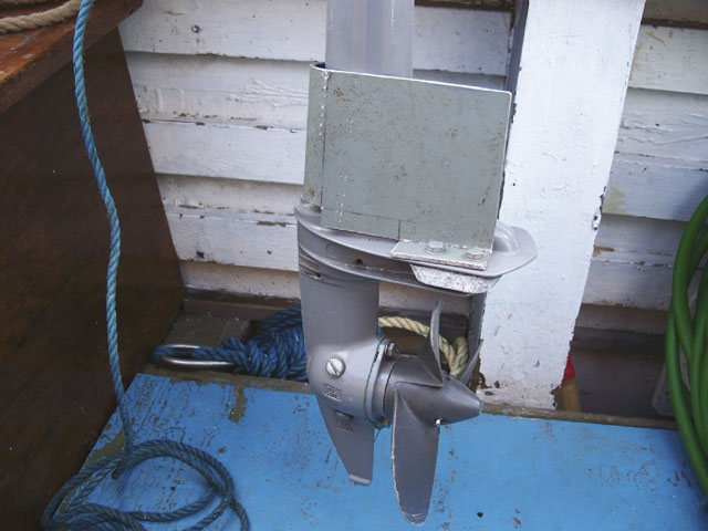
Check for play: Outboard rudders and rudders with a bottom bearing should be checked regularly for wear of pintles, gudgeons and other hardware by trying to rattle the rudder in its bearings. Spade rudders are supported by bearings inside the boat, so push the bottom of a spade rudder side to side to check for tube wear or other bearing problems.
So after all this research I came to the conclusion that perhaps we should use a different kind of bearing system.In the last 10 days I had dealt with and learned more about rudder bearings than in the previous 40 years and over 200,000 miles of off-shore sailing. After all, the rudder bearing is one of the simpler parts of any boat.
Have the boat yard lower the rudder slightly in relation to the upper bearing and check if the noise, vibration or squeak is gone. A Note About Grease - Only lubricate your rudder bearing if and where the manufacturer recommends. The rollers in a Jefa Rudder Bearing should never be greased. Self-aligning Jefa Bearings do require synthetic ...
Rudder Bearing Replacement. Happy Puppy was delivered with the factory standard bearings which really aren't bearings at all, but rather spherical polyethylene bushings. The lower bushing is mounted in a short fibreglass tube bonded to the bottom of the boat, while the upper unit is mounted to the underside of the deck using a rather Rube ...
We are back in our boat! This chapter is all about HOW TO REPLACE THE RUDDER BEARING on your own.If you have any questions feel free to ask us in the comment...
With a worldwide distribution network Thordon rudder bearings can be delivered fast to any ship repair facility in the world. Thordon SXL rudder bearings offer low friction, operating pressures up to 12 N/mm 2 (1740 psi) and the complete elimination of grease and greasing systems removing any risk of pollution. Thordon SXL can also withstand ...
The 20-knot semi-displacement lobster yacht's rudder I measured yielded an even 2.0 aspect ratio, which is considered respectable for this application. More identifiable rudder components include the stock; web or armature; rudderport or log; stuffing box or compression tube; bearing; gudgeon; and pintle. Not every rudder has all these ...
shaft bearings, rudder bearings and deck equipment bushings. Utilizing proprietary polymers, non-metallic Thordon bearings deliver smooth, reliable and quiet operation required for today's modern yachts. THORDON PROPELLER SHAFT BEARINGS Thordon offers three different propeller shaft bearing grades for different yacht operating profiles.
Bolt the rudder post bearing in upside-down, Six-10 the gap, and then pop it out before the Six-10 was fully cured to create a perfect, flush fit for the rudder post. Now, "all the components work as a system," as Brandon explained, to hold the rudder post firmly in place. Again, while it was a pretty extensive project, the knowledge ...
Pegasus yachts have a rather unusual rudder arrangement. A cast aluminium rudder horn, which forms the leading edge of the rudder for about half its depth, is bolted via a palm to the hull. At its lower end, a pintle bearing supports the rudder and takes most of the lateral rudder force.
With a little help from Nick, Julien explains and demonstrates how to replace the bottom rudder bearing onboard your X-Yacht.
Put " yacht grot " into Utube there is a good video on changing rudder bearing on a Bav 37. If that does not work put in " Bavaria rudder bearing " there is also a good water pump bearing change video. Utube has a lot of very good maintenance video's so it's always worth a punt looking them up. Hope this helps. Odysseus
On this map you can see the details of the longest and most classic of the Flotilla Radisson boat tours: 2. Companies that do boat tours on the Moskva River. There are many companies that do cruises on the Moskva River, but the 4 main ones are: Capital River Boat Tour Company (CCK) Mosflot. Flotilla Radisson.
Moscow river boat cruises — an unforgettable experience with Moskvatrip. A tourist won't embrace Russia wholeheartedly until he goes on a boat trip in Moscow. Enjoy the comfort of our luxury and safe vessels while another Moscow tourist attraction spreads before your eyes. Moskvatrip is your assistant in the choice of Moscow river cruises.
Radisson cruise from Gorky park. 2,5 hours. Yacht of the Radisson Royal flotilla. Best water route in Moscow. Panoramic views of the capital from the water in winter and in summer. Restaurant with signature cuisine. Next tour: 1600 ₽. Learn more.
A River boat cruise in Moscow is one of the most exciting tours you can do in the city. The boat ride on the Moskva river allows to see all the city embankme...