- 2024 BOAT BUYERS GUIDE
- Email Newsletters
- Boat of the Year
- 2024 Freshwater Boat and Gear Buyers Guide
- 2024 Boat Buyers Guide
- 2024 Water Sports Boat Buyers Guide
- 2023 Pontoon Boat Buyers Guide
- Cruising Boats
- Pontoon Boats
- Fishing Boats
- Personal Watercraft
- Water Sports
- Boat Walkthroughs
- What To Look For
- Best Marine Electronics & Technology
- Watersports Favorites Spring 2022
- Boating Lab
- Boating Safety

Locating Ground Faults (“Current Leaks”) and Short Circuits
- By Randy Vance
- Updated: July 28, 2010
Pervasive problems aboard boats are ground faults and short circuits. Both can slowly but surely drain the batteries, even with every switch turned off. Perhaps more important, these snafus can cause stray current corrosion, which can sink your boat by eroding away through-hull fittings, fasteners, rudders, shafts and drives. Here’s how to smoke them out and enjoy better service from the batteries. You’ll need a multimeter for both techniques.
Short Circuit
What it is: When a direct connection between the hot and ground sides of a circuit is made and it bypasses the load (light, pump, whatever).
How to find it: Disconnect the circuit from its power source — remove the terminals at the panel — and disconnect the load (device, or devices if they’re lights) from the circuit. Turn all switches for that circuit to the “on” position. Place the leads of the multimeter, set to the ohmmeter function, across the positive and negative sides of the circuit. A reading of infinite ohms means the circuit is good and the device is bad; a reading of less than infinity means there is a problem in the wiring.
Ground Fault
What it is: Poor, worn or chafed insulation on switches, devices or wiring allows a lower-resistance path to ground (usually bilge water) than the ground wire of the circuit does.
How to find it: 1. Switch off all equipment individually and disconnect solar panels. Leave the battery switch on. 2. Disconnect the positive battery cable and, with the meter set to the DC volts setting, take a voltage reading between the battery terminal and the cable. If it reads 12 volts — or any voltage, really — you have a leak. 3. Turn the battery switch off.
If… the leak still shows — you still read voltage — the leak is on the battery side of the switch. The only things that should be there — hot-wired to the battery — are the bilge pumps.
Then… rewire and reroute, supporting everything as high as possible.
If… closing the battery switch with the meter still connected to the post and disconnected, and if the leak “disappears” (no voltage reading), the leak is on the boat side of the system.
Then… to isolate it, keep the battery switch on, leave the meter connected and go to the fuse or breaker panel. Begin systematically closing breakers and pulling fuses. If the meter reads no voltage after breaking a circuit, that’s the guilty party.
If… the leak still shows, it’s one of the breakers or the panel itself that’s leaking.
Then… set the meter to ohms, and then systematically remove each breaker, testing across its terminals. With the breaker off, the reading should be infinite; if not, you have finally found the offender.
Tip: It’s often quicker to find many ground faults by simple visual observation, checking for any wires that have drooped into the bilge water or show obvious signs of chafe and wear, and then starting the meter readings with those circuits. Bilge, washdown or livewell pumps are common culprits — but not always.
- More: How-To , spring fitting-out , Troubleshooting
More How To

I Learned About Boating From This: Capsize, Rescue and Lessons Learned

Should You Abandon Ship During a Boat Fire?

38 Top Make-Ready Tips for the Spring Boating Season

On Board With: Andrew Robbins

We Test Interlux Trilux 33 Aerosol Antifouling Paint

Boating Shoes for Spring and Summer

MasterCraft Celebrates International Women’s Day With Fourth Annual ‘Let Her Rip’ Campaign

Garmin EchoMap Ultra 2 Series
- Digital Edition
- Customer Service
- Privacy Policy
- Terms of Use
- Cruising World
- Sailing World
- Salt Water Sportsman
- Sport Fishing
- Wakeboarding
Many products featured on this site were editorially chosen. Boating may receive financial compensation for products purchased through this site.
Copyright © 2024 Boating Firecrown . All rights reserved. Reproduction in whole or in part without permission is prohibited.
- Search forums
- Practical Boat Owner's Reader to Reader
What is an acceptable level of earth leakage?
- Thread starter Gerry
- Start date 18 Nov 2006
- 18 Nov 2006
Well-known member
Greetings A boat near mine is tripping the earth leakage detectors on the pontoon. The owner says that the current is only one mA and therefore no problem. PBO's book Electrics Afloat says 2OOmA at 60V is enough to kill. This is of some concern because I do dive on my boat to change anodes, clean the hull and so on. Does anyone know what is a lethal current at 110V and at 240V? What level of current, if not potentially lethal, is sufficient to create corrosion problems in nearby boats? What is the legal requirement? I know some marinas won't let you plug in if they detect any leakage at all. Once you are registering some leakage, is 1 mA to 200mA such a big step? I would welcome any thoughts on this. Gerry
Solent sailer
Active member.
Hello Anything over 15mA may kill, the voltage doesn’t matter it is only the "pressure" pushing the current and the current is what will kill you! The time is another critical factor which is why most domestic RCD's (residual current devices) as used on your lawn mower will normally trip within around 20mS. The BS standard or BSEN requires that this type of RCD operated within 40mS at 150mA. I would not expect any equipment on a boat to have any leakage, much of the electrical equipment at home will leak to earth typically electrical hot plates and computer equipment will have an earth leakage, the hot plates through degradation in the elements exacerbated by damp and not being used, computer equipment and some other electronic equipment like microwave ovens by the filter networks used in there power supplies. The minimum insulation resistance for an installation is 1Mohm this would give a leakage current of I = V / R 230/1000000=0.23mA. However it is permissible to have circuits that contain equipment with a high earth leakage and it is not necessary to carry out any special safety precaution unless the design leakage for the circuit is greater than 10mA. To sum up your friend is correct 1mA does not contravene any regulations (in my view) providing it is connected equipment causing the leakage and not the fixed wiring, if the leakage is caused by the electrical installation itself he may have a problem. Most electrical equipment used on a boat will be "Class 2" no earth used and protected by a second layer of insulation (battery chargers, fan heaters etc) which is why I am surprised the leakage current is so high. I am also curious how it was measured as obtaining an accurate earth leakage measurement with all the parallel paths available for earth leakage is not easy and I would be rather suspicious of any DIY readings quoted.
Hi Paul: You seem to know what you are talking about, but what if any use would a Galvanic Isolator be in this case and do they actually save the anodes. Regards... Peter
john_morris_uk
I know I am not Paul, but the answer is sort of embedded in Paul's original reply. Because of the multiple possible paths to earth, (including via your skin fittings and the surrounding sea-water) the Galvanic Isolator prevents small stray currents by requiring about 0.7 Volts to overcome the forward breakdown voltage of diodes. The diodes are wired in such a way that they don't (cannot) rectify the AC voltage, but do allow higher currents to pass and maintain the safety features of the installation and normal ground connection. The reason that they are so expensive is that they need to be proof against high overload currents. Diodes are very fats fuses if you are not careful.

I bow to Paul's obvious expertise, but am very skeptical about the boat owner's claim that the current is only 1 mA. I share Paul's doubts about the accuracy of this simply because most RCD units are rated to trip at higher current levels than that. It is possible that 1 mA will trip them, but I have my doubts wheter all are that sensitive. I think you need to complain to the Marina operator, especially if the tripped RCD is cutting the current to your boat as well as the offender.

[ QUOTE ] Galvanic Isolator prevents small stray currents by requiring about 0.7 Volts to overcome the forward breakdown voltage of diodes. The diodes are wired in such a way that they don't (cannot) rectify the AC voltage, but do allow higher currents to pass [/ QUOTE ] Thats almost right but not quite. Galvanic isolators block current from very low voltage sources (actually up to about double the figure you quote) but allow current from higher voltages sources (Eg mains electricity) to pass so that the effectivness of the earthing sytem and is maintained.

'In May 2002, a 14-year-old girl from Arlington, Texas, was electrocuted when wiring problems in an apartment swimming pool’s underwater lights charged the water with electricity. A 16-year-old boy was seriously shocked when he jumped in the pool to try to save the young girl. Another teenager used a fiberglass shepherd’s hook (a non-conductive device) to pull both victims from the water. ' Your question appears to be about the danger from stray currents to swimmers. This is the source story The owner needs to sort out his electrics. The marina are contributing to the risk by continuing to supply a faulty installation.
[ QUOTE ] [ QUOTE ] Galvanic Isolator prevents small stray currents by requiring about 0.7 Volts to overcome the forward breakdown voltage of diodes. The diodes are wired in such a way that they don't (cannot) rectify the AC voltage, but do allow higher currents to pass [/ QUOTE ] Thats almost right but not quite. Galvanic isolators block current from very low voltage sources (actually up to about double the figure you quote) but allow current from higher voltages sources (Eg mains electricity) to pass so that the effectivness of the earthing sytem and is maintained. [/ QUOTE ]Vic, perhaps you have phrased it better than me - tis what I was trying to say/thought I had said. I had SWMBO breathing down my neck saying 'we have to go NOW' as I was posting and couldn't re-read what I had written to see if it made sense!
If what he says is true,which I doubt, its 1mA today but what about tomorrow! it could be carbonisation of a component which will get worse, as others suggest I would have strong words with the marina.

Many thanks to you all for such informative replies. There are a couple of details I left out of my email because I did not want to load the question too strongly. There is not one but three boats on this pontoon with earth leakage faults. I know because I overheard the electricians shaking their heads about it when they came to find out why the alarms were going off. The manager of the marina has brushed their (and my) concerns aside. This might be because one of the boats that is leaking is his. I did not say anything, until I saw a diver in the water just by his boat. Whereupon I unplugged his boat and called him up on his mobile with my concerns about the leakage risk. His first question to me was how did I learn about the problem! He repeated that the earth leakage was only 1mA. What should I do now? Email his boss, the owner of the marina? Name and shame the marina? What do you suggest? Or am I just being paranoid? Also, any thoughts on what leakage current begins to present a corrosion problem for a nearby (possibly aluminium) boat?
If you believe that the marina is being mismanaged in this way your best recourse would be to contact the local regulatory authority in writing giving them all your available information so that they are in a position to investigate and then dismiss or act upon your concerns. If you are able to discover the tripping current on the RCDs and find that it is 10mA which gives a degree of personal protection you may rest more easily.
I had a further thought on this. If someone measured the earth leakage current they must have done so before the RCD tripped out, because afterwards there would have been no current. Therefore we cannot know what leakage current is actually causing the RCD to trip but it must be above the RCD trip point. The boats concerned need their elictrical systems sorting out as something on board has a serious and probably intermittent fault. In a marina, it is not mains leakage which is the main cause of galvanic corrosion. It is the fact that all boats with shore power are connected together via the earth wires in the power cable. The earth wires are also bonded to metal fittings. The result is that the marina becomes one giant galvanic battery in which an aluminium boat with inadequate anodes could well suffer. The seawater in this case is merely the electrolyte, with bronze propellers and the like acting as cathodes. I am not sure what effect mains to earth leakages have in this except that metal fittings below water on the boat with the leakage must be at risk.

Might be an idea to bang off a letter to the marina owner and copy it to, maybe, HSE and local electricity supply company, just to cover yourself, (esp if you or someone else has to make an insurance claim related to this in the future). I agree with the others about the 1mA - that's obviously a load of BS. If you know where the RCD is located,and have access to it, it will say on the label what the trip current is.

I think one of the problems causing earth currents is the marina wiring itself. In my marina I have disconnected the power cord and measured 7-volts AC between the shore power earth circuit (green wire) and the corresponding connection on my boat. Since the earth connection aboard my boat was connected to the engine block, this much voltage on the earth wire must have been driving substantial current into the surrounding waters. Unfortunately, I didn't have an AC ammeter to actually measure the current. Obviously a galvanic isolator could not block this much voltage. The standard here in North America is 120 volts between the hot wire (black) and the neutral wire (white). Normally there should be near zero volts between the neutral wire and the earth wire. However, because in a marina electrical installation there is considerable distance between the shore-side electrical distribution panel and the boat receptical, it's not unlikely that there is maybe 10 volts or so voltage drop on the two power wires. So it would not be unusual to expect up to 10 volts different between the neutral wire and the earth wire out at the sub-distribution panel near the boat. However, most such sub-distribution panels I've seen do not separate the earth wires (green) and the neutral wires (white) within this panel. They both connect to the same ground-connection busbar. Thus the green earth circuit can actually be maybe 10 volts above actual ground voltage where the boat is afloat. Now if you connect the green earth circuit to your engine ground, you can be electrolyzing the surrounding waters by that much voltage. [In the shore-side electrical panel, the neutral and earth circuits are tied together at the ground-bus with a substantial connection to a ground stake. Then out on the docks there are distribution sub-panels, but since this location is floating, there is no way to have a substantial ground stake. Most sub-panels that I've seen, tie the neutral circuit again to the earth circuit. Now, whatever voltage drop occurs normally between the shore panel and the dockside sub-panel, will produce some voltage between the earth wire and the actual earth where the boat floats.] The best way of isolating against this is probably by using an isolation transformer on the boat. Of course, earth leakage detectors will also provide protection against this, but I have never seen one in any of the marinas around here. I have actually made an earth leakage detector installed into a short section of power cord. I have checked my boat with it as well as the boats in the adjacent slips.
Currently, Im not aware of any requirement for boat mains electrcs to be periodically tested, but with all the extra mains kit that can be wired in these days, well worth considering. Orignal post says "earth leakage detector", but more likely to be an RCD these days (they work differently). Also, worth asking the "faulty" boat owner just how he can be sure his leakage currant is only 1 mA.
- 19 Nov 2006
As already questioned the owners claim that the earth leakage is only one milliamp is quite doubtful. One typical form of protection is sometimes known as core balance relay. Here current in the active wire is compared to the current in the neutral any difference is presumed to be going through earth and may be a human path so it disconnects. The device is tested by connecting a known resistor from active O/p to earth so providing a known unbalance current. This varies but 15 ma or so is a ball park figure. Unfortunately some equipment exhibits a fault which unbalances the currents and so causes the safety device to trip. This is usually more anoying than dangerous as the earth cable should dissipate the leakage current.. Your primary concern is that your power is being cut by a safety device which you share with other boats. You should not have to share as one device per boat would be far better and is more common. Certainly if your neighbour plugs his boat into the common circuit and the safety device trips then he has a problem which is causing you to lose power. it is very unlikely that this earth leakage current coulld ever do you any harm while in the water cleaning the hull etc. If it were a problem it would be only when you touched your prop which is connected to the mains earth via your power cable. So to be really safe disconnect the cable from your boat. Or more practically touch the prop initially with the back of your hand. A stated a galvanic isolator stops current from the earth of your power system (which can be every one elses earth as well) flowing to earth via the prop etc unless the voltage rises to what might be more like fault voltage ie above 1.4 volts. It is unlikely that high AC currents will cause electrolysis as the current is reversed 50 times per second. It is small stray DC currents that cause problems. These are usually gnerated by dissimilar metals but the effect can be made much worse by small DC currents which hopefully the galvanic isolator will stop. (The whole earewa of corrosion and current paths is very difficult to sort out)
William, here in the UK, the "core balance relay" is known as an RCD (residual current device") and because it is so common in domestic properties, there is a standard "off the shelf" bit of these kit for testing it in the manner that you refer to. The same kit also effectivelly fully tests the installation that is being supplied. Recent (Jan 2005) Government regulations ("part P") have enabled instrument companies to capitalise on this and packaged the test kit as a "multifunction tester" known as "16th edition tester"; I have one, a great piece of kit. Marina electrics is not yet effectively fully covered by "part P" (but new "reg's" due out next year may change that), although, with pleasure boats not requiring formal testing (yet), I guess it's up to the marina operators to police it. I agree, each berth supply should ideally have its own RCD but, for economy, here they tend to share them with a few other berths.
Why do we need to connect our boats to the mains earth at all? I know the basic safety argument, but RCD protection does not require earth connection. Think of the number of appliances on the domestic and garden market which only have 2 wire connection, can we not treat the boat as such thus removing the problem (which I have suffered ) of fast erosion of anodes due I believe to stray earth voltages in the marina. Both the marina and my boat have RCD protection. Do we need more?
Glad to hear that you have your own RCD on your boat, it’s a requirement already for caravans and motorhomes, but yet to see it mandatory for leisure boats. The 2 wire appliances that you refer to are known as “class 2” and do not rely on basic insulation alone (eg, may be double insulated or even isolated via a transformer). For the RCD to function, the “fault current” needs a path to earth, either a deliberate earth or perhaps an accidental one. You can only treat your boat as “class 2” if your installation is so constructed and this is not normally the case. As for mains ac contributing to “erosion of anodes”, see earlier posts.
Members online
- danieleither
- stevebrassett
- fredrussell
- Barton Seagoon
- Fr J Hackett
- cruisingsam
- pintsize555
- Appassionata
- SlowlyButSurely
- sailorbenji
Share this page
AC Ground Faults, the Boater, and ABYC—Understanding Equipment Leakage Circuit Interrupters (ELCIs) and Ground Fault Circuit Interrupters (GFCIs) to make your boat safer.
Related products.

However, if electricity “leaks” from this intended path in these two wires to ground, this condition is called a ground fault . A good example of this is an insulation failure in the wiring of an appliance.

Faulty grounds can be undetectable; a simple continuity test will not necessarily reveal a problem.
When these two conditions occur at the same time, the results may be tragic. The combination of a ground fault and a faulty ground can result in metal parts in the boat and under water becoming energized.
In addition to the hazard to people on the vessel, there is a larger danger to swimmers near the boat. While people on board are likely to receive a shock from touching energized metal parts, nearby swimmers could receive a paralyzing dose of electricity and drown due to involuntary loss of muscle control. A Coast Guard sponsored study showed numerous instances of electrical leakage causing drowning or potential drowning even though the shock did not directly cause electrocution.
Given the seriousness of the problem, ABYC requirements now include specific measures for avoiding this danger.
ABYC regulation E–13.3.5 states:
ABYC regulation E–11.11.1 states:
ELCIs, and the more familiar GFCIs, are part of a larger family of devices that measure current flow in the hot and neutral wires and immediately switch the electricity off if an imbalance of current flow is detected. ELCIs and GFCIs that are also Residual Current Circuit Breakers (RCBO) provide overcurrent tripping protection characteristic of a normal circuit breaker.
GFCIs are used as branch circuit ground fault protection at the 5mA threshold in potentially wet environments. GFCIs protect against flaws in devices plugged into them, but offer no protection from the danger of a failing hard-wired appliance, such as a water heater or cooktop.
In contrast, an ELCI provides additional whole-boat protection. Installed as required within 10' of the shore power inlet, an ELCI provides 30mA ground fault protection for the entire AC shore power system beyond the ELCI. ABYC regulations still require the use of GFCIs in environments described above.

Although ABYC regulations apply only to new boat construction, the dangers and liabilities exist for any boat owner with a shore power connection. Retrofitting an ELCI to an existing AC system can be worthwhile “insurance” against risk. Since an ELCI/RCBO can serve as the main shore power circuit breaker, it can replace a standard circuit breaker in this application. Alternatively, an ELCI/RCBO can be added between the shore power inlet and the existing main shore power circuit breaker.
Safety ground system failures on boats are safety and liability disasters waiting to happen. ELCI protection on each shore power line, combined with protection afforded by GFCIs, will reduce risk to those on the boat, the dock, and in the water surrounding the boat.

Technical Bulletin: Understanding AC Leakage Current

Editor’s Note: Gary Loftis of Maffett Loftis Engineering, LLC, is professional electrical engineer and a certified deputy electrical inspector with the State of Tennessee. He is a member of the International Association of Electrical Inspectors (IAEI) and has served as president of the Tennessee chapter, and is a member of the National Fire Protection Association (NFPA). Loftis is foremost concerned about marina safety and uses his knowledge and experience of marina electrical systems to ensure that electrical code requirements are effective, practical and economically feasible. With his vast experience in the field and the rise of electric shock drowning incidents, he gets many questions about how to measure current and how to detect leakage. In order to measure leakage current properly, marinas need an understanding of the basic principles of electricity. In today’s marina industry, many terms (such as GFCI, GFP, 100 milliamp (mA), 30 mA, ground faults, leakage current, etc.) are being thrown around without much understanding. In this article, Loftis will help shed light on this often misunderstood topic, explaining the basics behind leakage current and tips for effectively measuring it.
Technical papers and standards referenced in this bulletin are (1.) the 2017 NFPA 70 (National Electrical Code – NEC); (2.) US Coast Guard report, “In-Water Shock Hazard Mitigation;” (3.) ABYC E-11 “AC and DC Electrical Systems on Boats”, July 2015; and (4.) The Open University, PPLATO @ University of Reading, PHYS 4.2 Introducing Magnetism. Portions of these reference documents are directly quoted and/or graphics are used within this technical bulletin, as noted on each image.
The Fundamentals of Electricity In order to measure current traveling through a wire, a simple clamp-on amp-meter (such as the Fluke camp-on meter shown in the photo below) can be used. In this example, approximately 10 amps of current is flowing through the wire. However, the clamp-on amp-meter is not measuring current flow but is actually measuring the amount of magnetic field around the wire. One of the basic fundamentals of electricity is that when current flows through a wire, a magnetic field is produced around that wire. Figure 1 represents current flow through a wire and the resulting magnetic field.
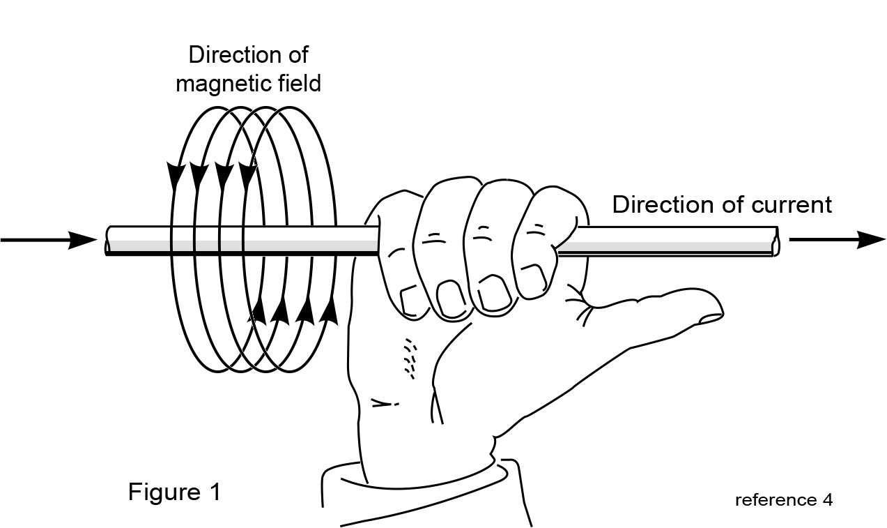
The intensity of the magnetic field is directly proportional to the amount of current flow. Therefore, the more current that is flowing through the wire, the greater the magnetic field.
The principle of magnetic fields is very important to grasp when trying to understand how to measure AC leakage current using clamp-on meters. These types of meters do not measure current flow. Instead, all clamp-on amp-meters measure the intensity of the magnetic field generated around the wire by the flow of current. Since the magnetic field is directly proportional to the amount of current flow in the wire, the clamp-on meter can be calibrated to display the amount of current in the wire based on the intensity of the magnetic field.
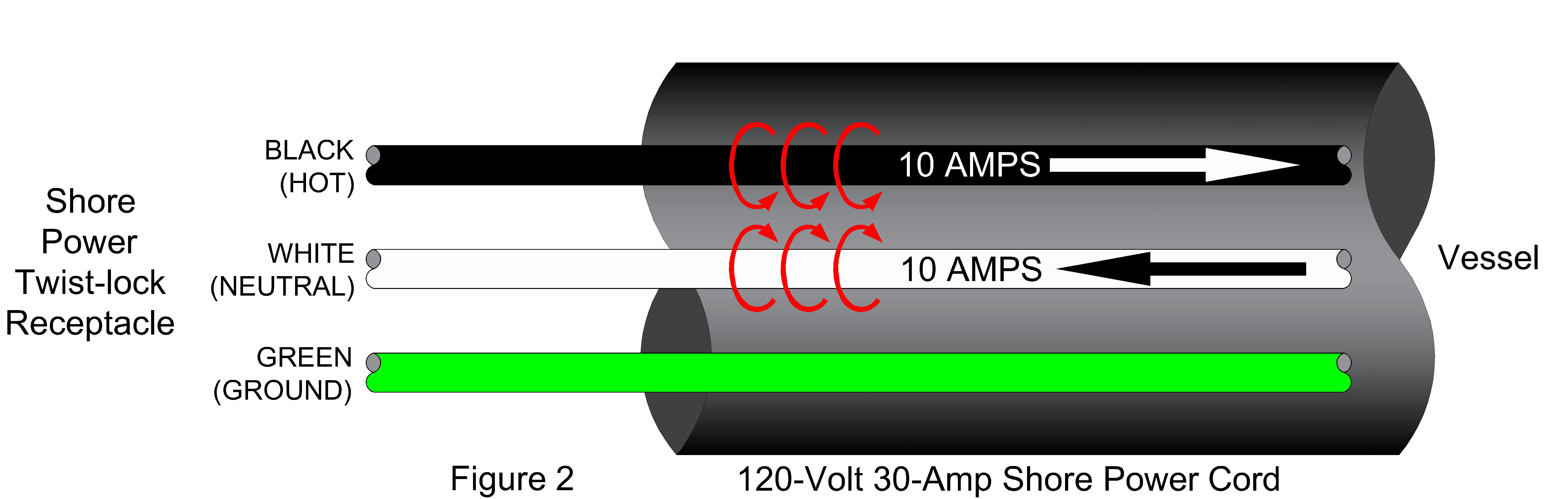
Using Fleming’s right-hand rule, the red arcs represent the direction of magnetic fields in both the black and white wires. If one were to hold his or her right hand up and point the thumb in the direction of the current in the black wire (refer to Figure 1 on page 38), the other four fingers show the direction of the magnetic field. Again, using the right hand, point the thumb in the direction of the current in the white wire. One will find the direction of magnetic field is in the opposite direction.
If a clamp-on meter is used to only measure the current in the black wire, the meter would read the intensity of the magnetic field around the black wire and would be calibrated to display 10-amps on the meter. The same goes for the white wire. If a clamp-on meter is used to only measure the current in the white wire, the meter would read the intensity of the magnetic field around the white wire and would display 10-amps on the meter.
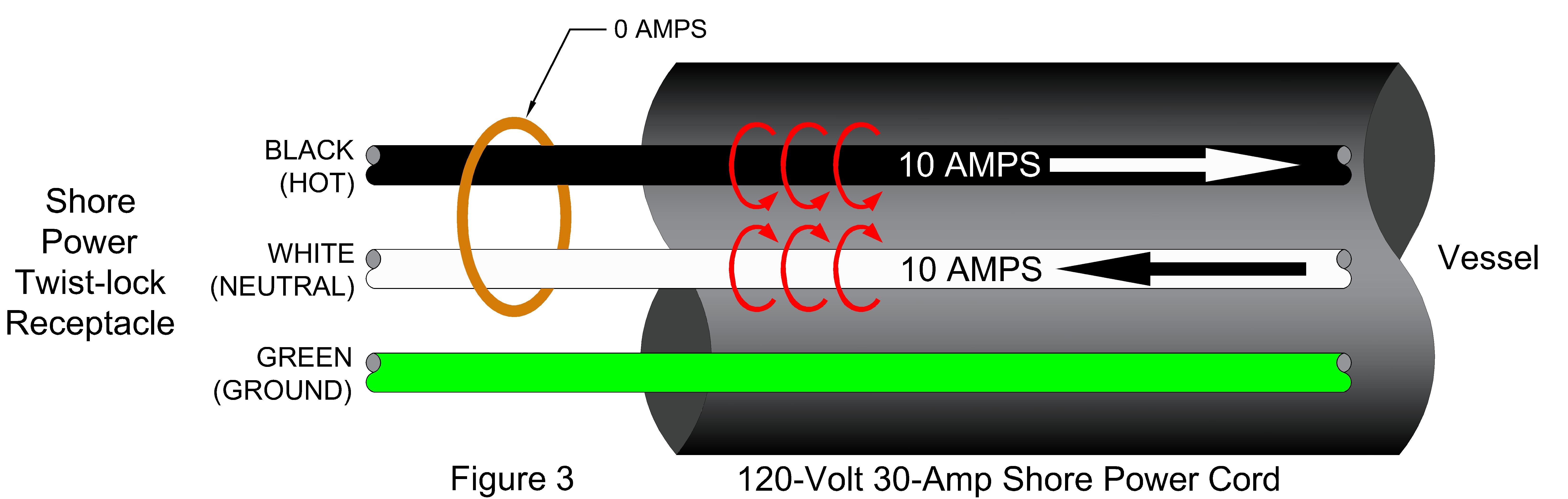
This photo shows the leakage current measurement of a 120-volt 30-amp shore power cord connected to a vessel. Clamping the meter around the entire shore power cord will measure the second scenario of leakage current noted above. As in the example above, the vessel connected to this shore power cord is leaking 100 mA of current into the environment.
When one takes a reading of leakage current, it is like taking a picture at a specific moment in time; after a brief moment in time, the scene changes. This is also true of the photo of the 100 mA reading. As soon as the meter is removed from the shore power cord, the leakage current can change. This is largely due to electrical equipment inside the vessel. For instance, the reading might be lower when the air conditioner is not running and higher when it is running. The same goes for all other pieces of equipment in the vessel.
The best scenario to measure the leakage current of a vessel is when all of the vessel’s electrical equipment is running, including all 120 and 240-volt equipment (including the DC to AC inverter). This will allow the leakage current meter to not only measure the wiring of the vessel, but also all of the electrical systems inside the equipment and fixtures.
The cause of leakage current is beyond the scope of this article. However, in some instances the age of the wiring systems and electrical equipment cause additional leakage current. As the insulation around a wire ages, the insulation properties begin to breakdown. Dry-rotting and cracking of the wire insulation can also cause additional leakage current.
Leakage current is sometimes caused by a high resistance short or a dead short. This scenario would be illustrated as when the black (hot) wire accidently comes into contact with a grounded object. This is called a ground fault. The next section covers ground faults in more detail and explains different levels of ground faults and their hazards to the human body. The leakage current measurement principle also works identically for a 240-volt 50-amp shore power electrical system.
Ground Faults A ground fault is defined in the National Electrical Code (NEC) as “an unintentional, electrically conductive connection between an ungrounded conductor of an electrical circuit and the normally non-current-carrying conductors, metallic enclosures, metallic raceways, metallic equipment or earth.”
Such involved and wordy definitions aid in most people having a hard time understanding electrical codes. This definition simply states that the black (hot) wire is leaking current to the grounding system. The grounding system includes the green (ground) wire and everything connected to it such as the aluminum vessel hull or metal structure of the dock.
Every electrical system has leakage current. It is the amount of the leakage current that is of major concern to the marina industry. Small levels of leakage current, typically less than 4 mA, should not cause any safety issues. Levels of leakage current above 4 mA are where safety concerns start to arise. In order to understand the different levels (or thresholds) of leakage current and safety issues associated with the human body, refer to the table on page 42.
The second line in the current thresholds table (i.e. 4 – 6 mA) is the amount of leakage current that is required for the tripping level of a Ground Fault Circuit Interrupter (GFCI) device. This GFCI device is the most common trip level that most everyone has experience with. A GFCI device is commonly found as a receptacle in your bathroom and kitchen with test and reset buttons on the front of the receptacle. A GFCI receptacle will trip power to the receptacle if there is an imbalance of current on the black (hot) and white (neutral) wires somewhere between 4 to 6 mA.
Any ground fault device that trips power when leakage current is greater than 6 mA is considered a Ground Fault Protection for Equipment (GFPE) device. However, in the NEC Article for marina codes (i.e. Article 555), the “E” is dropped and refers to these devices as Ground Fault Protection (GFP). Therefore, the 2017 NEC – Article 555.3 refers to a GFP device as a device with a leakage current trip level of 30 mA. Based on the information above, one should now understand this means there is a difference in current level between the black (hot) wire and the white (neutral) wire of 30 mA.
In all of the leakage current examples above, there is a 100 mA imbalance of current between the black and white wires. For reference, the previous 2011 and 2014 NEC Editions required a 100 mA GFP on marinas.
Correct Clamp-On Amp Meter Selection There are many clamp-on amp meters on the market. However, most are not suitable to be used as an AC leakage current meter. Going to a local electrical supply store and purchasing an off-the-shelf clamp-on meter generally is not the meter of choice.

Following is a list of meters that will measure in the low (or lower) mA range:
Yokogawa Clamp-on Tester Model No.: 30031A/30032A Leakage current measurement range: 3 mA – 60 A Diameter of measurable conductor/cable: 40 mm
Amprobe AC Leakage Clamp Model No.: AC50A Leakage current measurement range: 0 mA – 60 A Diameter of measurable conductor/cable: 30 mm
Fluke AC Leakage Current Clamp Model No.: 369 FC Leakage current measurement range: 3 mA – 60 A Diameter of measurable conductor/cable: 60 mm
Fluke AC Leakage Current Clamp Meter Model No.: 360 Leakage current measurement range: 3 mA – 60 A Diameter of measurable conductor/cable: 40 mm
Armada Tech True-RMS Milliamp Leakage Clamp Meter Model No.: PRO93 Leakage current measurement range: <1 mA – 100 A Diameter of measurable conductor/cable: 28 mm
The only clamp-on meter listed above that will allow the measurement of multiple 50-amp 240-volt shore power cords at one time is the Fluke 369 as it has a 60 mm clamp diameter. This clamp-on will also clamp around a 100-amp shore power cord. This function is useful if a marina has several vessels that have these larger power requirements.

There have been studies conducted to determine the amount of acceptable leakage current for a vessel while plugged in to shore power. The recommendation from the 2008 US Coast Guard report “In-Water Shock Hazard Mitigation” stated: “If AC leakage current is kept to less than 100 milliamps, a dangerous condition should not result around boats connected to the shore power system.”
As a result of this study, the 100 mA GFP requirement was added to the 2011 Edition of the NEC. The same requirement was kept in the 2014 Edition of the NEC.
Many in the code standards panels felt the 100 mA GFP requirement was not enough protection for vessels. Therefore, the American Boat and Yacht Council (ABYC) added a ground fault trip requirement to its E-11 Standard “AC and DC Electrical Systems on Boats” in the 2012 Edition. The following is taken from the ABYC E-11 Standard of July 2015: “11.11.1.1 – The trip level {of the GFP} shall be a maximum of 30mA. The trip time shall be a maximum of 100ms.”
Also, the latest 2017 Edition of the NEC has reduced the GFP requirement from the previous editions. Article 555.3 of the 2017 NEC states: “The overcurrent protective devices that supply the marina, boatyards, and commercial and noncommercial docking facilities shall have ground-fault protection not exceeding 30 mA.”
Furthermore, the 2008 U.S. Coast Guard report “In-Water Shock Hazard Mitigation” states: “30ma will result in 0.11V/foot. At these low current and voltage gradient levels…there should be no danger to anyone who may be in the water around a boat.”
By no means is this an invitation or otherwise a reason to grant permission to enter the water in a marina, even if the marina is equipped with a 30 mA GFP. Instead, what is being said is that a 30mA GFP should provide enough protection for a person if they accidently fall into the water at a marina.
Less than 30 mA of leakage current for a single vessel is within the acceptable range of safety standards.
Conclusion and Recommendations The following is a list of recommendations and requirements for consideration: • Only qualified electrical personnel should perform electrical work on marinas and vessels (including, but not limited to, the measuring of leakage current). • The proper understanding of how leakage current behaves is a requirement for anyone that desires to measure leakage current. • Install GFP on a marina’s electrical system per the NEC standards. • If a marina doesn’t have a GFP system installed, a routine should be started to measure for leakage current. Maintain a written log of the leakage current values for each vessel. • Per the NEC and ABYC standards noted in this article, a single vessel leaking 30 mA or more is not an acceptable amount of leakage current. • The most accurate means to measure leakage current is clamping around the hot and neutral conductors (see Figure 5). This can be performed by a qualified person within the shore power pedestal or by using an adaptor that has the individual insulated conductors exposed.
Gary Loftis of Maffett Loftis Engineering, LLC, is registered professional electrical engineer with more than 30 years of experience. For more about the technical bulletin, contact him at [email protected].
- Yachting Monthly
- Digital edition

Shorepower earthing question
- December 2, 2004
Should there be a connection between neutral and earth onboard my boat?
In the ‘Any questions?’ section of Yachting Monthly’s October 2004 edition, reader Richard Peperell raised a significant question regarding shorepower earthing which warranted a reply beyond the space available in the magazine. Here is the original question, along with Nigel Calder’s extended explanation.
Dear YM – I have a 52ft steel ketch with shorepower, connected through an isolating transformer and RCD (residual current device). In the March issue of YM’s ‘Any Questions’, Nigel Calder states there should not be an on-board connection between neutral and earth, but my research with the Metal Boat Society and Mastervolt suggests that the neutral and earth should be connected. Please could I hear Nigel’s views – perhaps this is an exception for metal boats?
Nigel also comments that reverse polarity does not create a hazard when an isolating transformer is fitted. Could he explain this, and also give me some tips on how to make or buy a reverse polarity tester?
Richard Peperell, via email
Nigel Calder replies: Earthing (grounding in US parlance) is difficult to address in a short note, especially given significant differences in the approach between Europeans and Americans. I hope the following will address the specific questions:
1. With an isolation transformer there is no direct connection between the shorepower circuit and the boat’s circuits – power is transferred magnetically. This has several beneficial effects, one of which is that the polarity of the on board circuits is established on board, and is not affected by the polarity of the shoreside connection. Given such a ‘polarized’ boat, a reverse polarity device is not needed. On other boats, all that is needed to test for reverse polarity is a high-impedance (at least 25,000 ohms in the USA – I’ll explain this in a moment) LED circuit between the neutral and earth circuits. If the polarity gets reversed on board, the neutral becomes ‘hot’ and the light now glows.
2. With an isolation transformer, the way polarity is established on board is by tying the neutral and the earth together at the transformer. In fact, the basic rule for all on board AC power is that the earth and neutral should be tied together at the generating source. In a typical installation (without an isolation transformer) the generating source is on shore (the neutral and earth are tied together at the dockside source), not on the boat, but with an on board AC generator, an isolation transformer, or a DC-to-AC inverter, these devices become the ‘generating source’ and as such the earth and neutral should be tied together at this point (or some electrical equivalent – normally the case of the device is used, but it could be a physically different point so long as it has the same electrical equivalence). I think Mastervolt, the Metal Boat Society and I are all saying the same thing, and maybe I wasn’t clear enough in my earlier comments about the distinction between typical shorepower installations and those with isolation transformers. If you have an isolation transformer, the neutral and earth should be tied together at the transformer.
3. A DC-to-AC inverter with a ‘pass-through’ capability (i.e. when the boat is plugged into shorepower, the inverter switches to shorepower) is an interesting situation. When in the ‘pass through’ mode (i.e. the boat is operating on shorepower) the neutral to earth connection must be at the generating source (shorepower, or the on board side of an isolation transformer if one is fitted) but when the inverter is supplying AC power it becomes the generating source, and as such the neutral to earth connection needs to be made at the inverter. Marine inverters have switches that make this connection when in invert mode and as such are different from many shoreside inverters. You should always buy a marine inverter for a boat.
4. The Europeans and Americans have different philosophies when it comes to RCD devices (which measure leakage of current from the ‘hot’ and neutral wires to earth, and trip when the current exceeds a certain level). In Europe, the trip limit is generally set at 30 mA (30 milliamps) whereas in the USA it is set at 5 mA as a result of tests conducted many years ago that established 5 mA as the level at which leakage current in the water began to effect muscle control in humans (this was determined by suspending student volunteers in a swimming pool and ramping up the current!). In the damp marine atmosphere 5 mA is low enough to be susceptible to nuisance trips, so the Americans protect individual outlets on the boat (this puts only one circuit, and the leakage current from that circuit, on each RCD, as opposed to putting the whole boat, with its accumulated leakage currents, on a single device) whereas the Europeans put the 30 mA RCD on the incoming shorepower line and use the single device to protect all the circuits on the boat. European standards then assume that this will protect against leaks to earth and as such when a whole boat RCD is fitted permit the boat to be wired without the AC earth circuits connected to DC negative (something that is otherwise important from a safety perspective). On boats that do not have an isolation transformer, not making this connection helps to prevent galvanic corrosion (especially important with metal boats). However, in the USA a considerable amount of data has been collected from domestic RCD use to show that failure rates are high (principally due to lightning-induced voltage surges) so even with a whole boat RCD the American standards advocate the AC earth to DC negative connection, and then recommend either a galvanic isolator, or an isolation transformer, to break the galvanic circuit back to shore. (I know some readers will be scratching their heads at this point! Galvanic isolation is a another complex topic I do not have space to address here.)
5. The minimum 25,000 ohm resistance on American reverse polarity devices is established by determining the resistance it will take on a 120 volt circuit to keep current flow below the 5 mA RCD threshold (otherwise the reverse polarity warning light, which makes a connection between the neutral and earth, would trip an RCD). At 120 volts, this is 24,000 ohms (120/0.005 = 24,000). Applying the same logic to a 30 mA RCD device on a 240 volt circuit, you arrive at 8,000 ohms (240/0.030 = 8,000) – i.e. the minimum resistance on a reverse polarity indicating circuit should be above 8,000 ohms.
6. Reverse polarity from other boats will not necessarily make the water live while concomitantly a boat without reverse polarity can make the water live. The basic rule is to not get in the water around boats plugged into shorepower! You can buy simple testers that plug into any receptacle to warn of various fault conditions – it is worth carrying one on board. You can make a crude test for voltage in the water by touching one probe of an AC voltmeter to any earthed circuit (e.g. the earth socket of a dockside outlet, so long as you know what you are doing and get the correct socket) and dangling the other probe in the water.
This stuff is difficult! I hope the above serves to elucidate rather than further confuse!!
- David Pascoe
- All Articles (over 180)
- Mid Size Power Boats
- Buyers' Guide to Outboard Boats
- Surveying Fiberglass Power Boats (2E)
- Marine Investigations
- Domestic (USA)
- International
- Privacy Policy
- All Articles
- Order Books
- Boat Reviews
- Buying a Boat
- Cores & Structural Issues
- Marine Engines
- Maintenance & Repairs
- Hull Blisters
- Marine Surveying
- Insurance Issues
- Boat Handling & Boat Safety
- Hurricane Preparations
- Fuel Issues

Read Online
Full Chapter One
- Dealing With Leaks
There is no point in doing anything on a boat unless you take the time to do it right. -- Anonymous
By david pascoe.
This article deals primarily with sailboat leak problems. However, the principles and methods discussed here apply equally well to power boats.
It's a fact of life that boats leak. It's also true that as boats age, leaks tend to increase for the simple reason that sailing yachts are under a lot of stress. And in these times when builders emphasize speed and lightweight, the problems with leaks worsen since laminates are not as thick nor are hulls as rigid as they used to be.
- Windows, Windows, Those Leaky, Leaking Windows
- How to Repair Window Leaks
- Is Your Boat a Leaky Tiki?
Leaks are not only inconvenient and aggravating, but also cause damage to personal gear and the boat itself. The source of leaks are usually hard to find and even harder to stop. The typical case is where the water enters at point A, but shows up at point B, which is six feet away from point A. The owner spends weeks attempting to search out the source so that he can repair it. These are usually instances where inner liners work to distribute the leaks to points far from the source of entry, and are often the subject of many wry jokes.
As an aside here, I want to mention something that I see very frequently that is just a waste of time and makes a mess of things. That is the way some people try to take the easy way out by just smearing some caulking on the outside of an open seam. On boats, to make an effective seal, the caulk has to go between the two parts that are mated, and this is called bedding. Achieving this is not easy, but it is the only way to effectively stop leaks. Moreover, with the way many boats are hurriedly built today, parts are often never bedded properly from the beginning. If that is the case, then you have to go back and do what the builder did not do correctly.
Of course, the granddaddy of all leaks is the leaky hull-to-deck join, which is usually the most difficult of all to repair. I've seen numerous boats where the deck joint leaks so bad that either the boat is uninhabitable, or the boat has become severely damaged as a result of rotting internal plywood structures, wet bedding and the like. Vee berths in both power and sail boats are often a victim of this problem, where you end up with both rotting mattresses and structures. Ouch! This gets expensive.
In many instances, the manner in which the deck is joined is such that effecting an economical repair is near impossible, or that the leakage is so pervasive -- meaning that the deck join is leaking everywhere -- that the deck needs to be removed and reinstalled anew, which also means that it's likely to be more economical to get rid of the boat and buy another one, than it is to attempt to repair it.
For these reasons, when considering the purchase of any used boat, it is of paramount importance to check the boat over for leaking deck joints; this is not a problem that anyone should buy into. Leaking deck joins are most intractable when associated with working hull structures. Not all boats are as rigid as they should be, and if the rigging is causing compression loading, both fore and aft, as well as transversely, then attempting to repair leaking deck joins may be an exercise in futility.
Checking a boat for leaks is fairly easy. Just start opening things up and looking. The usual indicators are, aside from the plainly obvious, are numerous rust stains where canned goods were stored, rusty tools and mattresses wet on the undersides. If not wet, look for stains on the hard berth surface. Check out any place on the interior of the hull sides where you may be able to see water trails or heavy amounts of mildew. Water stains on headliners, discolored cabin soles, damaged paneling, water puddles or water lines under berths or other places that trap water. The number of indicators is nearly endless.
It's a mistake to think that repairing leaks is a relatively minor problem that can be done at low cost. Yes, repairing a leak is usually a simple matter, but the fact is that there is often no access to the area that needs repair, so that to make the repair requires tearing out a part of the interior. Such is often the case with chain plates and other deck hardware.
Chain Plates
As any experienced sailor knows, the most common source of leakage is at the shroud chainplates where they pass through the deck. Because of the frequent loading/unloading that occurs at these points, it is very difficult to keep them sealed, and on some boats it is a constant battle. However, if the shroud chain plates are attached to plywood bulkheads, it is critical that the leaks be stopped and the wood protected. Due to poor design, for many boats it is impossible to keep the chain plates sealed completely, but there are things one can do to reduce the leakage and keep the plywood from rotting.
One of the most common mistakes that boat owners make is to caulk these points with the wrong material, most often polysulphides or silicone based caulks. These materials will not do the job because they have poor adhesive qualities. To create a strong, long lasting seal at a chain plate that is subject to working, one needs a strong, resilient adhesive. Such as the dreaded 3M 5200. Boat owners frequently tell me that they hate using the stuff because it's messy, and because once applied, it's very difficult to remove or detach parts bedded with it. But that is precisely why it should be used; 5200 is one of the strongest adhesives available and adheres very well to metals and nearly all other materials other than some vinyls and polypropylenes. Polysulphide "sealers" are not good adhesives and silicone is not an adhesive at all. It's primary means of adhesion is suction. That's why you can glue glass together with it, but nothing else, for only glass will yield a perfect suction surface. If you ever wondered how they can glue aquariums together with silicone, that's the reason why.
5200 is like working with tar. It has a way of getting all over everything, no matter how hard you try to be careful. That's one of the reasons it's so good; it sticks to anything and everything. When working with the stuff, you should have plenty of rags and a quart of acetone handy. Once you've used a rag to wipe up excess, get rid of that rag as that rag will transfer 5200 to everything it comes in contact with, including you. It's a real tarbaby. Clean your hands the moment you get some on them, otherwise your fingers will transfer it to whatever you touch. You won't notice this at first, but weeks later dirty finger prints will start showing up all over, and they do not wipe off. Once it's cured, 5200 is no longer soluable with anything.
If your bedding or caulking material does not adhere to a part, though it may appear to cling closely, what we end up with is a minute crevice between caulk and the mating surface. In turn, this crevice becomes a capillary that is capable of transporting water in amazing quantities through a crevice so small that it may not even be visible.
Therefore, one of the best ways of sealing up leaky chain plates at the point where they pass through the deck is to thoroughly clean the fiberglass surfaces, preferably with something like a Dremmel tool with grinder bit to get a good bonding surface. Don't waste you time trying to caulk over a dirt laden surface, you efforts to seal will fail. Plus you must be sure that there is no waxy or oily residue. Thus, it's best to sand or grind all surfaces to be bonded.
Often times the width or length of the rectangular hole is too large to be able to fill it in adequately. If that's the case, you can glue in appropriately sized filler strips with 5200 so as to reduce the gap between the chain plate and deck. Once the 5200 has cured, then you can come back and apply the final bead of caulk, and bed down the rectangular flange plate if there is one. Because of the strength and durability of 5200, this method should last for many years assuming that there is not excessive structural movement involved.
If the chainplate is attached to a plywood bulkhead, it's a good idea to treat the area to prevent deterioration. A successful method I have used is to unbolt the plate, grind down the surface to get it good and rough, and then coat the area and bolt holes with epoxy. This will help shed water and greatly reduce the potential for rot if the attempts at sealing the leaks are not successful.
Stanchion Bases and Other Hardware
The next most common source of leakage are those pesky lifeline stanchions. These stanchions are subject to an incredible amount of stress, so that over time even the best installations will begin to leak. However, I see far too many boats where the basic design of the base is poor. The foot print of the base is often so small that it has little or no chance of providing a stable attachment. If that's the case, the only option is to change them out, if possible.
Properly repairing leaking stanchions often becomes a nightmare job because the boat builder has provided no access from the underside. If you can reach the under side, the job is fairly easy. First, the bases should be removed entirely. Check to see that the bolt holes are properly sized to the bolts. If the holes are oversized, a rigid attachment cannot be obtained. Correct this by completely filling the holes with epoxy and milled fibers; then redrill the holes (using a drill guide) to their proper size. Lightly sand the outer surface to remove dirt and mold release compound that may still be present. If the base did not have a back up plate, you should add one, space permitting. Aluminum or a blank of scrap laminate will work fine. Use the stanchion base as a pattern to drill the holes. Don't use plywood with nuts and washers as these will crush the plywood and permit loosening.
Again, the material to use for bedding stanchion bases is 5200. Both the stanchion base and the back up plate on the underside should be thoroughly bedded as this will create a double seal. When pushing the bolts down through the holes, and while the head is standing proud about 1/4", make sure that there is bedding under the head. If not, add some.
Deck Drainage
I don't know what it is about sail boat designers, but they seem to have a superb knack of overlooking deck drainage. As I make my rounds through marinas and boat yards, it's amazing the number of boats I see with water standing on the decks. When hardware is present, leaks are sure to follow, which are also a serious hazard to cored decks. One way or another, you have to find a way to provide adequate drainage, whether by notching the rail or installing a scupper.
Ports, Windows and Hatches
These tend to develop leaks because the structures to which they are attached are not completely rigid and are subject to movement, thus breaking the bedding seals. This is often the case with port holes in the sides of cabin trunks. Jumping on the deck near them results in flexing that breaks the seal. Many boat owners just smear some caulking around the exterior seam. All this will do is create an unsightly mess, but will not stop leaks.
The bedding seals in port holes break loose because a non adhesive bedding compound was used to set them, usually because the ports are plastic. The common reasoning for this runs, "Well, these parts are plastic and if I use 5200 they will never come off without breaking. Therefore, I will use polysulphide or silicone." That is true, but what you've now got is leaks, so it's your choice between leaks and costly interior damage, and parts that come off easily. It's true that if you bed a plastic port with 5200, you may end up destroying the port trying to get it off. On the other hand, if you use 5200 and bed it properly, you shouldn't ever have to deal with leaks again.
If the flexing is excessive, there will be essentially no way to stop the leaks short of reinforcing the flexing area. This is a fairly common problem with side decks adjacent to trunk cabins, and around hatches set in a wide expanse of deck; if the deck flexes at all, the hatch or port won't stay sealed.
Alternative Methods
Whenever you suspect that slightly flexing structures are the primary cause of leaks, such as hatches on deck or coach roof, or port holes in a cabin trunk or even hull side, try jumping on the deck or stressing the surface by some method to see how much it flexes. If flexing is only moderate, an alternative method of leak stoppage may be appropriate. Instead of bedding and bolting the part down hard with wet bedding, in which case you squeeze most of the bedding out, leaving only a thin film of bedding that will seal less well, try using this method of creating a gasketed joint, which usually takes two persons to accomplish. For this method, you can use any high quality flexible caulk rather than 5200.
Cut a number of shims of equal thickness, say 1/8". Apply the bedding thickly and evenly around the mating surface using a putty knife to smooth it out to slightly more than that thickness. Use a new putty knife and wax it so the caulk doesn't stick to it. While you begin to set the hatch or port frame in place, have the other person shim it all around. The objective here is to create a layer of bedding of uniform thickness by using the shims and excess of caulk that will serve as a flexible gasket. The idea is that if there is structural movement, rather than creating a rigid joint that is going to break loose, we create a more flexible join by this method.
Obviously, great care has to be taken that there are no big bubbles or voids between the hatch frame and caulking layer. Set the hatch frame in place, and press down until the shims stop it. A lot of caulk should be squeezing out the sides. Next, run all the screws or bolts in, but do not draw them tight. Leave enough space under the heads that more caulk can be added. Now, allow the bedding to fully cure, at which point you come back , recaulk under the bolt heads, and then draw them tight. What you have done is to create a gasket. If leaks redevelop due to a flexing structure, you can come back and retighten the fasteners.
Note: When retorquing the fasteners, be especially careful with cast aluminum or plastic flange plates; if torqued too much or unevenly, they are likely to crack or break. Extruded aluminum will not break, but you do run the risk of distorting the flange if torqued too much or unevenly.
These are another common leakage problem. Because the leakage occurs within the rope locker where leaks usually do not cause interior water damage, the leaks often cause severe damage to the windlass drive motor and housing. Windlasses usually develop leaks because they are highly stressed, breaking the seal around the deck and bolts. If you don't already have leaks, you can usually avoid them by being careful not to place very heavy loads on the windlass. Don't use it to force out stuck anchors.
There is only one solution for curing leaks around the windlass base, and that is to pull it and rebed it. Not a pleasant task, but keep in mind that just smearing some caulk around the base won't help. Very often, I find that the real cause is that the builder failed to provide an adequate foundation for it during construction. In other cases, the builder cored the foundation area with plywood, but the windlass installer failed to thoroughly caulk the bolts with 5200 and water got into the plywood and rotted it. Whatever the cause, you need to evaluate the source of the problem and correct it.
Leaking Packing Glands
It is often a great mystery to boat owners why they suffer from chronic packing gland leakage after repeated repackings and tightenings. Some try converting to the "dripless" type of glands and still that doesn't solve the problem.
Chronic packing gland leakage is usually the result of excessively flexible engine mounts on diesel engines. Because small diesels cause a lot more vibration than larger diesels, sail boat builders prefer to use softer mounts which allow for more engine movement. Engine movement, of course, causes shaft misalignment which, in turn, causes packing glands to leak because the shaft is spinning eccentrically and wears the packing out more rapidly on one side. This, in turn, usually results in rapid cutless bearing wear which results in even more shaft movement, at which point even freshly repacked glands won't end the leakage.
Obviously, there is no particularly good solution because you will have to trade off higher vibration levels with stiffer mounts to achieve less leakage. Whatever you do, don't switch to an expensive dripless type of gland because the shaft misalignment caused by flexible engine mounts will damage it and it will be a wasted effort. If the engine mounts are very old, say ten years or more, it's a good idea to replace them. Replace cutless bearings at the point where you can move the shaft in the bearing.
Shaft concentricity can be easily checked without the use of a dial indicator. If the shaft is dirty, clean it off with sandpaper while it is rotating until you get a nice, shiny surface. A shaft that is running out of true as little as 0.010' is plainly visible. At 0.020" out of concentricity is unmistakable and at 800RPM you will notice the wobble. If so, you need look no further as to why you have leakage problems. But why is it wobbling? Is it a bent shaft, or the result of engine movement?
A good way to find out is to directly observe how much engine movement or vibration is occurring. This, too, is usually plainly obvious. Check this at various engine speeds. Usually the largest amount of movement will occur within the lower half of the RPM range, and tend to go away at higher speeds. If the shaft is bent, the eccentricity will become a blur but not go away. The strong vibration will increase. If you put your hand on the stuffing box, or the transmission, you will feel it. If the wobble smoothes out and the vibration tends to lessen, then the shaft is not bent and the mounts are the likely culprit.
If the engine mounts prove to be too flexible, it's a good idea to change them out to a more rigid type.
Thru-hull Fittings
With today's modern materials and cored hulls, leaking thru-hull fittings is not a problem in and of itself. But it is a problem that threatens water intrusion into cored structures of all types, including decks.
To eliminate this danger, it is only necessary to adhere to a very simple rule: Never, but NEVER install a through hull fitting or fastener directly into or through a cored structure. Also, never install a through hull on a surface with a pronounced curve. Otherwise, it will no seal properly, or, if you draw it too tight, it will cause a dimple in the hull skin. The proper method of ensuring that water never gets into a core is to never breach the core. When it comes to through hull fittings, especially if you have to add one, this is not as difficult proposition as it may seem, though it's a bit more time consuming than for a non-cored structure where you just drill a hole and pop it in. The entire job takes about 4 hours over two days, not including time to obtain materials.
The first thing is to remove the core from the immediate area where the sea cock or whatever will be installed. This is done from the interior. Let's say, for example, that you are going to install a sea cock that has a 2" diameter foot print. You'll need to remove about a 6" square of inner laminate and core. There are a variety of means to do this, depending on working space available. Usually a die or angle grinder with abrasive cutting disc will work fine in tight spaces. Cut through the inner laminate only and remove the square of inner skin only. Next, cut out the core with a knife in a circular shape. The reason for this is that is necessary to relaminate and completely seal up the exposed areas of the core. It's a lot easier laminating the rounded corners than it is a square one.
Next, using an 80 grit grinding pad on a very small grinder, you smooth out all surfaces in preparation for closing up the exposed edges, keeping in mind that the laminating surfaces must be absolutely clean, and the bottom of the hole must be flat.
There are several ways to finish up here. The method I prefer is to use a high quality marine epoxy paste and 2 or 4 oz. Cloth. Don't use mat because you'll end up with a big mess. Trowel the paste heavily onto the edges of the core, working it into the cells and rounding out the corners at the bottom. Use more rather than less epoxy. It will help to round over the top corner of the expose foam. Then I cut the cloth to the appropriate size -- meaning about a 1" overlap each onto the inner skin and outer skin, and then press these strips into the wet epoxy completely around the circumference of the cut out. Following this, you then trowel the remainder of the epoxy paste onto the outer side of the fabric, making sure that there are no holes or gaps, and then smooth it out. I use latex gloves and smear the epoxy around with my fingers. Note here that you must use fresh two part epoxy for this job, not old stuff that has become thick and stiff.
This method will ensure that there is no chance that water will leak into the core, because you have completely sealed it off. Once it's cured, come back with the grinder and smooth out irregularities. Now you're almost ready to drill your hole for the new sea cock and install it in the usual manner, but there is another important detail to attend to. That is providing a doubler block under the sea cock so as to relieve strain on the outer skin.
What to use for the doubler? Well, the ideal material would be a piece of fiberglass laminate scrounged from a boat yard or trash can. Or any other type of reinforced plastic that is 1/4" to 1/2" thick. The doubler should be about 1" larger than the foot print of the sea cock and be completely flat. It's best to bed this in place with epoxy, let it cure, and then drill the hole through both parts at once to get the best fit. Now you're ready to install the sea cock and never have to worry about it leaking.
Posted December 23, 2000

David Pascoe - Biography
David Pascoe is a second generation marine surveyor in his family who began his surveying career at age 16 as an apprentice in 1965 as the era of wooden boats was drawing to a close.
Certified by the National Association of Marine Surveyors in 1972, he has conducted over 5,000 pre purchase surveys in addition to having conducted hundreds of boating accident investigations, including fires, sinkings, hull failures and machinery failure analysis.
Over forty years of knowledge and experience are brought to bear in following books. David Pascoe is the author of:
- " Mid Size Power Boats " (2003)
- " Buyers’ Guide to Outboard Boats " (2002)
- " Surveying Fiberglass Power Boats " (2001, 2nd Edition - 2005)
- " Marine Investigations " (2004).
In addition to readers in the United States, boaters and boat industry professionals worldwide from nearly 80 countries have purchased David Pascoe's books, since introduction of his first book in 2001.
In 2012, David Pascoe has retired from marine surveying business at age 65.
On November 23rd, 2018, David Pascoe has passed away at age 71.
Biography - Long version
Maintenance, Repair Articles At A Glance
- All about Bilge Pumps
- Attaching Hardware to Your Boat
- Battery Basics
- Corrosion in Marinas
- Diesel Maintenance, Or Lack of It
- Electronics Outside
- Haul Out Basics
- How to Install an Aluminum Fuel Tank
- How to Prevent Your Boat from Sinking
- Tips on Electrical System Use and Maintenance
- Maintaining Stern Drives
- Maintenance Fundamentals Part I : Engines
- Myth of Condensation in Fuel Tanks, The
- Preventing Rot in Encapsulated Wood Structures
- Repairing Diaphragm Pumps
- Repairing Rotary Vane Pumps
- Solving Chronic Battery Problems
- Tips on Painting Fiberglass Boats
- Winter Lay Up
- Washing Down
- From Other Category
- Exhaust Risers (from Buying a Boat Cat.)

- What is Pre-Purchase Survey?
- Business Practices and Client Relations
- Sound vs. Seaworthiness
- Hull and Its Structure
- Surveying the Hull
- Using Moisture Meters
- Stress Cracks & Surface Irregularities
- Deck & Superstructure
- Drive Train
- Gas Engines
- Fuel Systems
- Exhaust Systems
- Electrical Systems
- Plumbing Systems

- The Marine Investigator Read Online Full Chapter 1
- The Nature of Investigations
- The Nature of Evidence
- Marine Insurance and Issues of Law
- Bilge Pumps & Batteries
- Finding the Leak
- Sinking Due To Rain
- Fire Investigations
- Machinery Failure Analysis
- Fraud Investigations
- Interrogation Techniques
- Deposition & Court Testimony

Published by: D. H. Pascoe & Co., Inc. Articles, Images: Copyright © 1997 - 2018 David H. Pascoe All rights reserved. Articles, Images: Copyright © 2019-2022 Junko A. Pascoe All rights reserved. Web site design & developement: Copyright © 1997 - 2023 Junko A. Pascoe All rights reserved. Web site: Maintained by Junko A. Pascoe
Service Locator
- Angler Endorsement
- Boat Towing Coverage
- Mechanical Breakdown
- Insurance Requirements in Mexico
- Agreed Hull Value
- Actual Cash Value
- Liability Only
- Insurance Payment Options
- Claims Information
- Towing Service Agreement
- Membership Plans
- Boat Show Tickets
- BoatUS Boats For Sale
- Membership Payment Options
- Consumer Affairs
- Boat Documentation Requirements
- Installation Instructions
- Shipping & Handling Information
- Contact Boat Lettering
- End User Agreement
- Frequently Asked Questions
- Vessel Documentation
- BoatUS Foundation
- Government Affairs
- Powercruisers
- Buying & Selling Advice
- Maintenance
- Tow Vehicles
- Make & Create
- Makeovers & Refitting
- Accessories
- Electronics
- Skills, Tips, Tools
- Spring Preparation
- Winterization
- Boaters’ Rights
- Environment & Clean Water
- Boat Safety
- Navigational Hazards
- Personal Safety
- Batteries & Onboard Power
- Motors, Engines, Propulsion
- Best Day on the Water
- Books & Movies
- Communication & Etiquette
- Contests & Sweepstakes
- Colleges & Tech Schools
- Food, Drink, Entertainment
- New To Boating
- Travel & Destinations
- Watersports
- Anchors & Anchoring
- Boat Handling
- ← Safety & Prevention
How To Control Electrical Flow On Your Boat
Advertisement
Isolation transformers can prevent electric shock drowning, protect underwater metals on your boat, and avoid reverse polarity when plugging into shore power.

Installing an isolation transformer on any boat with a shore power connection prevents galvanic corrosion, reverse polarity issues, and protects swimmers near your boat from electric shock drowning. | Photo: ©2019 Erich Stevens
Water leaking into a boat signifies a problem that'll likely grab your attention pretty quickly. But there's another type of leak that you can't see, but could prove potentially deadly — electricity.
Any boat plugged into shore power has a potential for problems, but these can be largely eliminated thanks to a device called an isolation transformer. With an isolation transformer installed, you can protect your boat from the wasting of underwater metals due to galvanic corrosion, reverse polarity problems, and protect swimmers near your boat from electric shock drowning (ESD). Here's how they work and why you might want to install one.
It Starts With The Green Wire
One of the wires that helps to make your shore power system safe is the green wire, or the grounding conductor. The importance of this wire cannot be understated — it saves lives! The green grounding conductor wire does not normally carry any current, but should there be an electrical fault or short circuit on board, the grounding wire will take the fault current safely back to ground at the source of power. But if this vital green wire is compromised, the stray current will seek to return to its source to complete the circuit by some other route, likely through the water via the boat's underwater metal parts, which can prove fatal to swimmers in the water near the boat.
Even when the green wire works as planned, it's important to understand that every boat plugged into shore power at a marina is electrically connected to one another via the green grounding wire. The unfortunate reality is that it is quite common for low levels of electrical current, both AC and DC, to leak and travel from one boat to another via this green wire. At very low levels (less than 30 milliamps) this can be considered a normal condition. But even without current leakage present, two boats plugged in at the same dock, one with an aluminum outdrive in the water and another with a bronze propeller submerged, are connected via this green wire and make up a perfect galvanic cell — think of it like a giant battery. With both boats connected via the green wire it's more than possible for the aluminum drive to start eroding because it is made of a less noble material than the bronze prop. If there is some way to safely disconnect that green wire, the circuit will be broken and the aluminum drive will be protected. But how can you disconnect this wire to protect your underwater metals and still be safe?
Well, there is one piece of equipment you can install on your boat that will fix all these issues and more: an isolation transformer.

Isolation transformers work by induction. Electricity flowing through one coil creates electricity in the other with no physical connection.
The (Missing) Link
Essentially, an isolation transformer electrically disconnects your boat from shore power. It's installed aboard the boat between the shore power inlet and the boat's main AC distribution panel and works on the well-known principle of magnetic induction. In its most basic form, an isolation transformer is merely two large coils of wire wrapped around iron cores that are rigidly held in close proximity to one another. Running shore power AC voltage through one of the coils creates a strong, pulsating electromagnet near the second coil of wire ( see illustration above ). This pulsating electromagnetic field induces electric current flow in the transformer's secondary windings, and it is this secondary coil that supplies voltage to the boat's AC panel.
The beauty in this technology is that by using magnetic induction, there is no hard wiring connection between the boat's onboard 120- or 240-volt electrical systems and the dock. The transformer enables removal of one of the components needed to complete the galvanic cell mentioned earlier, a hard-wired connection of two or more dissimilar metals, thus shutting down any voltage migration from the dock side to the boat side of the transformer that can cause your underwater metals to erode. If the secondary side of the transformer is correctly wired, leaking current simply returns to the transformer on the boat via the green grounding conductor, not through the water, which would endanger swimmers. (See "Prevent Electric Shock Drowning" below for more information on ESD.)
In addition, a common dock wiring issue, reverse polarity, is eliminated because the transformer is self-polarizing. If you connect to a dock where the hot and neutral wires are reversed, the transformer doesn't care, and you will still have a good, clean source of AC power aboard.
Prevent Electric Shock Drowning
Most of us know how important the green ground shore power wire is. It carries fault current (electricity that's going somewhere it's not supposed to) back to shore, where it can't hurt anyone.
But marina shore power systems may be less-than-reliable. Due to long-term corrosion or improper installation, the ground wires are sometimes not properly connected, meaning you (and nearby swimmers) are not protected from a fault if the AC shore power shorts into the DC system. This could happen because of a problem in any AC/DC appliance, such as a battery charger. If that happens, any fault current is going to follow a path all through the boat's DC ground and bonding system, which is connected to the engine and underwater fittings, such as thru-hulls and prop shafts.
Because leaking current always searches for a way back to its source (in this case, the marina's shore power system ashore), leaking current will exit the boat and head toward shore. If a swimmer passes through the current, he or she will be electrocuted and may be killed. This is called Electric Shock Drowning (ESD) , and every year people die this way. The beauty of an isolation transformer is that because it has taken over duties as the boat's power source, any leaking current will simply return to the transformer on the boat, protecting everyone in the water.
Is It For You?
As much as I would love to see every boat with shore power have an installed isolation transformer for the reasons noted above, reality gets in the way. Isolation transformers are typically heavy, weighing in the 80- to 200-pound range, take up a significant amount of space, get quite hot while running, and can be rather expensive. Bear in mind that if your boat has more than one shore power input, twin 30-amp connections are fairly common, you'll need an isolation transformer for each line, doubling the weight and cost. So they're not for every boat.
That said, if you have a mid- to large-sized boat and regularly connect to shore power, an isolation transformer will enhance your shore power system and onboard safety. Costs range from about $600 on up, plus installation, though the peace of mind may be well worth the price.
Related Articles
The truth about ceramic coatings for boats.
Our editor investigates the marketing claims of consumer-grade ceramic coatings.
Fine-Tune Your Side Scan Fishfinder
Take your side-scanning fishfinder off auto mode, and you’ll be spotting your prey from afar in no time
DIY Boat Foam Decking
Closed-cell foam flooring helps make boating more comfortable. Here’s how to install it on your vessel
Click to explore related articles
Contributor, BoatUS Magazine
Ed Sherman is an avid boater and the author of "The Twelve Volt Bible for Boats," "The Power Boater’s Guide to Electrical Systems," and "Advanced Marine Electrics and Electronics Troubleshooting." He's the former vice president and education director of ABYC.
BoatUS Magazine Is A Benefit Of BoatUS Membership
Membership Benefits Include:
Subscription to the print version of BoatUS Magazine
4% back on purchases from West Marine stores or online at WestMarine.com
Discounts on fuel, transient slips, repairs and more at over 1,200 businesses
Deals on cruises, charters, car rentals, hotel stays and more…
All for only $25/year!
We use cookies to enhance your visit to our website and to improve your experience. By continuing to use our website, you’re agreeing to our cookie policy.
Does Your boat have Earth Leakage? (Bet you don’t know)
Jun 21, 2017
Let me ask you a question.
Does YOUR boat have electrical earth leakage? Chances are that, like most boaters, you don’t know.
DC Earth Leakage….

Hull corrosion can be caused by DC Earth Leakage. The corrosion can happen very quickly. Although it’s a similar process to galvanic corrosion, it often happens much faster.
Usually the pitting is light to begin with, but rapidly becomes much more severe, and can soon lead to a “Sweating” hull. Actually, a sweating hull is much more serious than it might sound, as the “sweating” is actually water entering through microscopic perforations in areas where the metal is heavily corroded.
Eats Anodes

So, if your anodes aren’t lasting as long as you expect, this is often a sign of Earth Leakage.
Unfortunately, many boats don’t have sufficient anodes fitted to provide adequate protection, so even boats with new anodes can be damaged by Earth Leakage.
Corrodes Propellers

However, the damage doesn’t stop there, because the corrosion often extends to the propeller shaft and bearings.
This is made worse by the fact that a corroded propeller is often out of balance, and can cause vibration.
The MASSIVE problem with DC Earth Leakage is that most people have never even heard of it. From our experience we believe that more than 1 in 3 boats have earth leakage problems.
One of the main causes of Earth Leakage is the technical equipment that we have on our boats, that can send pulses of leakage through the boats electrical system – even when they are working perfectly .
If you have Earth Leakage problems, you almost certainly won’t know about it! DC Earth Leakage will NOT blow a fuse, and it will NOT trip a circuit breaker.

With one of our latest Galvanic Isolators with Status Alert, you would know about Earth Leakage before it could damage your boat. We also provide a simple to follow fault finding guide, and in most cases, you’ll be able to rectify the problem yourself – quickly and easily.
Our Galvanic Isolator with Status alert will tell you if your boat is at risk – AND it protects you from Galvanic Erosion too.
More information right HERE
Already got a Galvanic Isolator? Check out our earth Leakage Tester HERE
- • Galvanic Corrosion and Earth Leakage on Boats
- • Galvanic Isolator solution for corrosion on boats
- • Galvanic Isolators for All Boats – Made in UK
- • Galvanic Isolator (Wouldn’t have helped the Titanic)
- • Stop Galvanic Corrosion on Boats
- How To Choose
- Galvanic Isolator Testing
- Galvanic Isolator 101
- Plug In Instructions
- Wire In Instructions
- Accessories Etc.
Buy Worldwide


Rosatom Starts Production of Rare-Earth Magnets for Wind Power Generation
TVEL Fuel Company of Rosatom has started gradual localization of rare-earth magnets manufacturing for wind power plants generators. The first sets of magnets have been manufactured and shipped to the customer.

In total, the contract between Elemash Magnit LLC (an enterprise of TVEL Fuel Company of Rosatom in Elektrostal, Moscow region) and Red Wind B.V. (a joint venture of NovaWind JSC and the Dutch company Lagerwey) foresees manufacturing and supply over 200 sets of magnets. One set is designed to produce one power generator.
“The project includes gradual localization of magnets manufacturing in Russia, decreasing dependence on imports. We consider production of magnets as a promising sector for TVEL’s metallurgical business development. In this regard, our company does have the relevant research and technological expertise for creation of Russia’s first large-scale full cycle production of permanent rare-earth magnets,” commented Natalia Nikipelova, President of TVEL JSC.
“NovaWind, as the nuclear industry integrator for wind power projects, not only made-up an efficient supply chain, but also contributed to the development of inter-divisional cooperation and new expertise of Rosatom enterprises. TVEL has mastered a unique technology for the production of magnets for wind turbine generators. These technologies will be undoubtedly in demand in other areas as well,” noted Alexander Korchagin, Director General of NovaWind JSC.
For reference:
TVEL Fuel Company of Rosatom incorporates enterprises for the fabrication of nuclear fuel, conversion and enrichment of uranium, production of gas centrifuges, as well as research and design organizations. It is the only supplier of nuclear fuel for Russian nuclear power plants. TVEL Fuel Company of Rosatom provides nuclear fuel for 73 power reactors in 13 countries worldwide, research reactors in eight countries, as well as transport reactors of the Russian nuclear fleet. Every sixth power reactor in the world operates on fuel manufactured by TVEL. www.tvel.ru
NovaWind JSC is a division of Rosatom; its primary objective is to consolidate the State Corporation's efforts in advanced segments and technological platforms of the electric power sector. The company was founded in 2017. NovaWind consolidates all of the Rosatom’s wind energy assets – from design and construction to power engineering and operation of wind farms.
Overall, by 2023, enterprises operating under the management of NovaWind JSC, will install 1 GW of wind farms. http://novawind.ru
Elemash Magnit LLC is a subsidiary of Kovrov Mechanical Plant (an enterprise of the TVEL Fuel Company of Rosatom) and its main supplier of magnets for production of gas centrifuges. The company also produces magnets for other industries, in particular, for the automotive
industry. The production facilities of Elemash Magnit LLC are located in the city of Elektrostal, Moscow Region, at the site of Elemash Machine-Building Plant (a nuclear fuel fabrication facility of TVEL Fuel Company).
Rosatom is a global actor on the world’s nuclear technology market. Its leading edge stems from a number of competitive strengths, one of which is assets and competences at hand in all nuclear segments. Rosatom incorporates companies from all stages of the technological chain, such as uranium mining and enrichment, nuclear fuel fabrication, equipment manufacture and engineering, operation of nuclear power plants, and management of spent nuclear fuel and nuclear waste. Nowadays, Rosatom brings together about 350 enterprises and organizations with the workforce above 250 K. https://rosatom.ru/en/

U.S. Added Less New Wind Power in 2021 Than the Previous Year — Here’s Why

Norway’s Massive Floating Wind Turbine Wall Will Be Funded by the Government This Year

Top 10 Countries in Wind Energy Capacity

RWE Becomes a Top Tier Renewable Energy Company in the United States

Renew Power Deploys India’s 1st 3X Platform Wind Turbine Generators

Highest Self-Supported Wind Tower Ever Built
You are using an outdated browser. Please upgrade your browser or activate Google Chrome Frame to improve your experience.
- Link to search page
- US: +1 (561) 833 4462
- US: +1 (206) 209-1920
- MC: +377 99 90 74 63
Yachts for Sale Moscow
We currently have no yachts to show. Please check back again soon.
COMMENTS
1. Switch off all equipment individually and disconnect solar panels. Leave the battery switch on. 2. Disconnect the positive battery cable and, with the meter set to the DC volts setting, take a voltage reading between the battery terminal and the cable. If it reads 12 volts — or any voltage, really — you have a leak.
Gerry. A boat near mine is tripping the earth leakage detectors on the pontoon. The owner says that the current is only one mA and therefore no problem. PBO's book Electrics Afloat says 2OOmA at 60V is enough to kill. This is of some concern because I do dive on my boat to change anodes, clean the hull and so on.
A Coast Guard sponsored study showed numerous instances of electrical leakage causing drowning or potential drowning even though the shock did not directly cause electrocution. Given the seriousness of the problem, ABYC requirements now include specific measures for avoiding this danger. ABYC regulation E-13.3.5 states:
Tips to install shore power on a yacht. Do. Buy the right capacity and type of cable for each job. Keep the cable from inlet to RCD as short as possible (max 3m) Segregate all AC wiring from the DC and install separate switch panels. Clearly mark all AC devices and cables with warning labels.
Therefore, the American Boat and Yacht Council (ABYC) added a ground fault trip requirement to its E-11 Standard "AC and DC Electrical Systems on Boats" in the 2012 Edition. The following is taken from the ABYC E-11 Standard of July 2015: "11.11.1.1 - The trip level {of the GFP} shall be a maximum of 30mA.
The steps for seeing if you have a DC-ground leak are as follows: First-the preliminary diagnosis test: 1) Turn off all equipment and disconnect any solar panels. 2) Disconnect the positive side of the battery banks. 3) Leave the main battery isolation switch turned on for the bank in question.
Leakage current is cumulative in a grounding system, whether on board the boat or on the dock. The National Electric Code (NEC) requires 5 mA-rated GFCI devices for all 15- or 20 amp service receptacles on a dock. This will work just fine for a small center-console boat with no more than, say, a 120 volt battery charger as an appliance on board ...
Typical shorepower, 120-volt alternating current (120V AC), relies on three wires: black (hot), white (neutral), and green (grounding). The black wire works in concert with the white to bring the shorepower to your boat. If all goes according to plan, the green wire will never carry any current or do any "work.".
In the damp marine atmosphere 5 mA is low enough to be susceptible to nuisance trips, so the Americans protect individual outlets on the boat (this puts only one circuit, and the leakage current from that circuit, on each RCD, as opposed to putting the whole boat, with its accumulated leakage currents, on a single device) whereas the Europeans ...
If it feels wet, move in for a closer inspection. Use the paper towel to dry off the hull and the fitting, and inspect closely using the flashlight. Look for the first appearance of a trickle or drip. Dry it again and verify you are seeing the first point of emergence. Use the mirror to check the backside of the fitting.
The National Electrical Code Article 555 addresses electrical shock drownings caused by leakage of electrical current from A/C shore power facilities on docks and marinas. Concurrently, the American Boat & Yacht Council (ABYC) section E-11.11 has made changes to address A/C power leakage from boats into surrounding waters that endanger people.
This article deals primarily with sailboat leak problems. However, the principles and methods discussed here apply equally well to power boats. It's a fact of life that boats leak. It's also true that as boats age, leaks tend to increase for he simple reason that sailing yachts are under a lot of stress. And in these times when builders emphasize speed and light weight, the problems with leaks ...
This pulsating electromagnetic field induces electric current flow in the transformer's secondary windings, and it is this secondary coil that supplies voltage to the boat's AC panel. The beauty in this technology is that by using magnetic induction, there is no hard wiring connection between the boat's onboard 120- or 240-volt electrical ...
Maximum values of earth leakage for appliances are identified below, it is important to remember these are maximum values: For class II appliances and for parts of class II construction - 0.25 mA. For class 0, 0I and III appliances: 0.5 mA b for class I portable appliances -, 0.75 mA. For class I fixed motor-operated appliances - 3.5 mA.
The MASSIVE problem with DC Earth Leakage is that most people have never even heard of it. From our experience we believe that more than 1 in 3 boats have earth leakage problems. One of the main causes of Earth Leakage is the technical equipment that we have on our boats, that can send pulses of leakage through the boats electrical system ...
Exploring intentional earth leakage current and how it can affect the design and operation of your electrical installation.What are the recommendations in BS...
Earth Leakage Relays act as vigilant guardians, constantly monitoring electrical circuits for irregularities. The moment a leakage is detected, the relay acts promptly, mitigating potential risks ...
Neutral earth. Operating frame. For a 230 V phase/neutral voltage network in a TT system, the IEC 60364 standard. connection. earth connection. requires a maximum breaking time of 200 ms. For the 2.1 A leakage current: an instantaneous residual current device with a sensitivity of 300 mA will power.
06 Nov 2020 by Rosatom. TVEL Fuel Company of Rosatom has started gradual localization of rare-earth magnets manufacturing for wind power plants generators. The first sets of magnets have been manufactured and shipped to the customer. In total, the contract between Elemash Magnit LLC (an enterprise of TVEL Fuel Company of Rosatom in Elektrostal ...
Every yacht for sale in moscow listed here. Every boat has beautiful hi-res images, deck-plans, detailed descriptions & videos.
Billionaire Roman Abramovich owns nine mansions in four countries, seven apartments and shares in seven companies, but no yachts and no airplanes, according to an official income declaration.. The ...
Russia Yacht Charter, Moscow, Russia. 120 likes. Организация отдыха, обучения на парусных яхтах. Семейные ...