Service Locator
- Angler Endorsement
- Boat Towing Coverage
- Mechanical Breakdown
- Insurance Requirements in Mexico
- Agreed Hull Value
- Actual Cash Value
- Liability Only
- Insurance Payment Options
- Claims Information
- Towing Service Agreement
- Membership Plans
- Boat Show Tickets
- BoatUS Boats For Sale
- Membership Payment Options
- Consumer Affairs
- Boat Documentation Requirements
- Installation Instructions
- Shipping & Handling Information
- Contact Boat Lettering
- End User Agreement
- Frequently Asked Questions
- Vessel Documentation
- BoatUS Foundation
- Government Affairs
- Powercruisers
- Buying & Selling Advice
- Maintenance
- Tow Vehicles
- Make & Create
- Makeovers & Refitting
- Accessories
- Electronics
- Skills, Tips, Tools
- Spring Preparation
- Winterization
- Boaters’ Rights
- Environment & Clean Water
- Boat Safety
- Navigational Hazards
- Personal Safety
- Batteries & Onboard Power
- Motors, Engines, Propulsion
- Best Day on the Water
- Books & Movies
- Communication & Etiquette
- Contests & Sweepstakes
- Colleges & Tech Schools
- Food, Drink, Entertainment
- New To Boating
- Travel & Destinations
- Watersports
- Anchors & Anchoring
- Boat Handling

Create Your Own Wiring Diagram
Advertisement

Photo: Ed Sherman
Whether you want to install a new stereo system or trace an intermittent electrical fault, a wiring diagram will save you hours of aggravation. The older your boat, the more likely you are to have either no wiring diagram or one that's worse than none because it's inaccurate. Making your own isn't rocket science, but it does take time, patience, and care. You won't get it all done in a day — or even several weekends — and don't let yourself get intimidated by complex electrical diagrams. Start by focusing on the simpler (and safer) 12-volt DC system aboard your boat. With each wire you trace, and circuit you complete, it gets easier. Eventually you'll have a map of your entire electrical system and a thorough understanding of how the pieces are tied together.
On many boats there are two types of current: alternating (AC) and direct (DC). Serious damage and even electrocution can result from confusing the two. In recently built boats, the two systems should be clearly differentiated and separated, including at the electrical panel. Wires and components associated with each should be distinct and, on newer boats built to American Boat and Yacht Council (ABYC) standards, will use standard color-coding. See chart at below.
AC wiring for 110 volts usually has white for neutral, black for hot, and green for ground (220-volt AC lines have a second hot wire, colored red). Those three wires typically are enclosed in white or gray insulation. You'll see the colored individual wires when they exit the common sheathing at each end. Your diagram should have one line for those three enclosed wires, except as necessary to differentiate them at the ends.
The wiring colors on your boat may be very different, especially if it's older and there's been a lot of "jury rigging" in its past. Make no assumptions about which wires do what. Trace each wire in the circuit from the electrical source to its use. Wire colors will assist you in doing that, even if they don't follow ABYC standards, by helping you identify the far end where it reappears from a conduit or a locker on its way to the equipment it powers.
On boats with both AC and DC systems, the DC system is generally simpler. DC power originates from the battery banks, so there is only one source. The DC electrical system is grounded through the negative bus of the distribution panel, which in turn is grounded through the engine negative terminal or its bus. That means that only two wires run from the distribution panel to each consumer of DC power — a DC positive and a DC negative — versus the three or four wires for each AC electrical user. The simplicity of the DC system, along with its relative safety in comparison to AC, makes it a good place to start.
Tip: Be very careful; don't confuse black DC negative wires on older boats with hot black wires on an AC circuit.
Big Picture: Sources & Uses
Take a careful look at the electrical systems on your boat, listing sources and uses for both AC and DC current. If it runs without the inverter when only battery power is available, it belongs on the DC list. A general idea of how each is connected will help you anticipate what to draw. If you have a good wiring diagram, copy it and blow it up so that you can make clear notes and changes in the future. Anytime you change the wiring or electrical components, write it on the diagram. If you don't have a good diagram, or you're intimidated by the arcane electrical symbols on the one you have, make one from scratch using large paper.
Starting with the batteries, follow the wires through to the end users, noting the selector equipment and any other equipment in line. Some people draw the wires within a sketch of their boat to indicate where they are. In a complex boat, this may ultimately be more confusing than drawing them in abstract and using industry conventions to show electrical components (see Online Extra). Start simply and make sure you know what you're drawing. Use a sharp pencil and try to avoid erasures. As you gain understanding and confidence, you'll likely redraw it several times. Indicate wire colors and gauges (thickness). The lower the gauge, the thicker the wire and the more current it can carry. The gauge should be imprinted on the insulation, with the number followed by "AWG," such as "12 AWG."
Using the list you made for the DC side, match up the breakers on the panel to the DC users. A few stragglers aside, the diagram of your DC system should come into focus. But don't jump ahead and make assumptions. All too often, a circuit breaker will have been reassigned in some past renovation, or a previous owner will have spliced into a wire to obtain power for an added item such as a fan. The only way to figure that out is to trace each wire to see where it really goes.
Tracing A Wire
After getting a basic understanding of your DC system, it's time to get down and dirty. First turn off all sources of power. Unplug from shore power, turn off any inverter and disconnect it from the battery, disable the generator, and remove the positive DC wires from the batteries. Although you're working on DC circuits, these actions will disable the AC side in case you mix up the two. Even after you've done this, DO NOT assume it's safe to touch any exposed wires, terminals, bus, etc.
Start at the source and trace each wire through to its end. The primary source wires will be heavy-duty wires running from your batteries to a distribution panel, or on smaller boats, a busbar. These wires should be few and simple, and much heavier gauge than the ones coming out of the panel/busbar because they supply the current for all those smaller wires. They may run through a selector switch before the panel.
The busbars or circuit breaker panels are the secondary source for most of your wiring, where the current "spreads out" following myriads of smaller wires to all the users on the boat. Hopefully your panel will have labels at the breakers, giving you some idea where these wires go. You may have to cut wire ties to isolate a particular wire contained in a tight bundle. Remember to re-tie the bundles when you're through. The wire you're tracing will often lead into a hole or conduit, but its color should distinguish it at the other end. If not, position a helper where you think the wire exits. Pull or carefully tug on your end, and hopefully your helper can see it moving. If not, try pulling back and forth like a seesaw.
If you just can't trace a wire, use a volt-ohm meter (VOM) to check for continuity (see "Five Ways To Use A Digital Multimeter," Dec. 2013). If you get continuity, you know in theory that the wire coming out of the hole is the same one going in. In some cases, wires going to certain equipment can indicate "ghost continuity" because of ground connections or other features. Physically tracing the wire is the most accurate method, especially on older boats. Once you've identified a wire from its source to its use, you can label it and add it to your wiring diagram.
Labeling And Diagramming
Attach labels to the wires at each end and at appropriate spots along the wire run. This helps when troubleshooting later. Buy labels or use high-quality yellow or white electrical tape and write on it with a quality indelible marker. Oil, grease, and other fumes in the boating atmosphere can cause the glue on labels or even good electrical tape to dissolve.
It's usually best to wrap the tape entirely around the wire, sticking it to itself. Office supply labels for label printers look neat but I've found that the glue on the back seldom lasts long and the labels end up in the bilge. Also label the wires and components on your diagram. You'll probably have to list and number these labels off to the side with a corresponding encircled number at the component. This avoids diagram clutter.
As you trace wires, look carefully for problems, including chafed insulation, hot spots indicated by browned or blackened insulation, little bumps in the insulation (indicates corrosion or overheating inside), a burnt insulation smell, or corroded terminals. Note the problems and fix them before you use the boat again. If you find an unfamiliar component, such as a diode, shunt, or transfer-solenoid switch, ask someone or research the part until you know what it does. This isn't just for accuracy; it will educate you, enabling you to diagnose problems more easily.
In older boats you might find dead wires, where an owner has removed something and disconnected (hopefully) its supply wire at the panel, but left it behind "just in case." Should you take it out, leave a strong nylon messenger string in its place to pull through another wire later. If you leave the wire, label it at both ends and be certain it's dead. Seal each end by wrapping it with electrical tape and then smear electrician's "liquid tape" over the actual tape to keep moisture out and the tape in place.
Voilá! The Final Product
By the time you get through diagramming the DC system, you'll have a good sense of how you want your wiring diagram to look. This is a good time to redraw it before starting on the AC system. AC systems can have more than one source (shore power, generator, inverter). If yours is particularly complex, consider hiring an ABYC-certified tech for an hour or two to walk you through it. Your diagram should clearly differentiate between AC and DC, or you can do a separate diagram for each system. Label which is which and make it obvious where the two types of current run close to, or could be confused with, each other. Make at least one copy to keep off the boat, and store your onboard diagram in a waterproof container such as a Ziploc bag. If it's very large, roll it up in a PVC pipe with two end caps. Glue one on, and use the other as a removable cap.
Diagramming your electrical system is a great winter project, and will be invaluable when you want to install something new.
Example Of A Draft Wiring Diagram For A Simple Boat
- When you make your own wiring diagram use very large sheets of paper for clarity.
- Most boats will have positive and negative busses where area wires come together.
- Equipment coming off a switchboard or circuit panel should be straightforward to trace.
- On a small boat, sketching circuits in the boat outline helps you locate wires later.
- The next step would be to trace the wiring to the instrument cluster and related gauges.
- Start with large cables leading from the batteries to the selector switch/busses.
Related Articles
The truth about ceramic coatings for boats.
Our editor investigates the marketing claims of consumer-grade ceramic coatings.
Fine-Tune Your Side Scan Fishfinder
Take your side-scanning fishfinder off auto mode, and you’ll be spotting your prey from afar in no time
DIY Boat Foam Decking
Closed-cell foam flooring helps make boating more comfortable. Here’s how to install it on your vessel
Click to explore related articles
Technical Editor, BoatUS Magazine
One of the top technical experts in the marine industry, Tom Neale, BoatUS Magazine Technical Editor, has won nine first-place awards from Boating Writers International, and is author of the magazine’s popular "Ask The Experts" column. His depth of technical knowledge comes from living aboard various boats with his family for more than 30 years, cruising far and wide, and essentially learning how to install, fix, and rebuild every system onboard himself. A lawyer by training, for most of his career Tom has been an editor and columnist at national magazines such as Cruising World, PassageMaker, and Soundings. He wrote the acclaimed memoir All In The Same Boat (McGraw Hill), as well as Chesapeake Bay Cruising Guide, Vol. 1. These days, Tom and his wife Mel enjoy cruising their 2006 Camano 41 Chez Nous with their grandchildren.
BoatUS Magazine Is A Benefit Of BoatUS Membership
Membership Benefits Include:
Subscription to the print version of BoatUS Magazine
4% back on purchases from West Marine stores or online at WestMarine.com
Discounts on fuel, transient slips, repairs and more at over 1,200 businesses
Deals on cruises, charters, car rentals, hotel stays and more…
All for only $25/year!
We use cookies to enhance your visit to our website and to improve your experience. By continuing to use our website, you’re agreeing to our cookie policy.
Practical Boat Owner
- Digital edition

Understanding electrical wiring connections for boats
- Pat Manley and Oliver Ballam
- August 16, 2023
Pat Manley and Oliver Ballam demystify boat electrics and explain how to use and make secure electrical wiring connections

Protecting a connector with spray grease. Credit: Fernhurst Credit: Fernhurst
How to make and use electrical wiring connections for boats
Connections are the heart of the electrical system and if we’re not meticulous in making them, they can be its downfall.
- They must be secure.
- They must be supported so that the wiring is not taking any load which might make it liable to being pulled out.
- They must be protected from corrosion .
- They must be accessible.
- They should be identifiable.
Corrosion is the enemy of all cable joints on a boat. Any exposed cable joint should be protected using silicone grease.
The connection may be a joint between just two wires or a joint between multiple wires.

These connector blocks have a clamping leaf which is pushed down by the screw to hold the wire. Credit: Fernhurst
There are a number of different ways to make the joints and you need to consider if the joint is to be permanent or if it needs to be undone from time to time.
The strongest permanent joint, having the least electrical resistance, is a soldered joint made on new, bright wire.

Electrical wiring connections: Without a clamping leaf, as here, there is a risk of breaking the strands of wire. Credit: Fernhurst
However, a soldered joint may melt in the event of a short circuit. Signal wires are small in diameter because they carry a very small current.
They are typically used for instrument wiring and are fairly fragile, so they need special consideration when being joined.

Alternatively there are Wago blocks which don’t use screws, but have a spring contact. Credit: Fernhurst
There are two schools of thought on whether the end of a wire should be ‘tinned’ with solder or not.
Soldered joints use a flux to remove oxidisation from the surfaces to be joined.

Marine grade ‘bus bar’ connector. Credit: Fernhurst
This flux may be acidic and can cause subsequent weakening of the wire.
On small-diameter, multi-strand wire, stresses can be induced by movement at the junction of the soldered wire and the unsoldered wire.

Electrical wiring connections: Multiway connector block. Credit: Fernhurst
The screw of a screw terminal and the crimping process are both unable to ‘squash’ the soldered part of the cable and joints may be less secure.
Most technicians recommend that the ends of the wires should not be soldered.
Electrical wiring connections: Terminal blocks
Also known as ‘chocolate block’ or ‘strip connectors’.
These allow joints to be made and remade as required. Select the appropriate-sized terminal block for the wires to be connected.
Using a wire stripper, remove just sufficient insulation to fit into the terminal.

‘Chocolate block’ connectors – no good for damp places. Credit: Fernhurst
Insert the wire into the terminal and tighten the clamping screw, ensuring that the screw presses down on the centre of the wire’s core.
‘Chocolate block’ connectors are not ideal for use on a boat, unless in a very dry area.
If used, both the wire entries and screw heads must be insulated against moisture ingress with spray grease to prevent corrosion of the cable.

Use crimp eye terminals – no more than four to a single screw or post. Credit: Fernhurst
Do not try to keep moisture out by wrapping it with self-adhesive electrical tape.
Connector blocks or strips should be made from marine-grade materials, which rules out those bought from the local car shop.

Non-ratchet crimping tool. Credit: Fernhurst
If they’re to be used with small-diameter signal wires, such as those used for instrument connections, they should have a clamping leaf to hold the wire, otherwise the wire’s strands may be broken as you tighten the securing screw.
Connection of signal wires is probably the most useful application on board for ‘choc-block’ connectors.

The better ratchet crimping tool. Credit: Fernhurst
For power connections, marine-grade ‘bus bar’ connectors should be used with crimped terminals on the wires, preferably self-sealing ones.
Never wind a wire around a bolt and screw the nut down on top of it – always use a crimped eye terminal.
This is to ensure proper contact and security of the joint. Do not fit more than four eyes to a single screw or post.
Types of electrical wiring connections
Crimped connectors come in a variety of shapes and three different colour-coded sizes.
Using an oversized connector will make a weak joint. Using an undersized connector will mean not all of the strands of the wire will fit into the part which is crimped, making this a bad connection.
So you need to use the correct size connector for the wire being connected.
Crimping tools and connectors are available cheaply from car shops.

The much better double crimp (left) and the cheaper single crimp (right). Credit: Fernhurst
The connectors may be made of steel and/or the metal will be too thin, preventing an adequate crimp pressure.
Most of these are a single crimp, meaning they have one metal ring which is crimped onto the conductor.
The better, more expensive, crimp terminals have two rings – one crimps onto the conductor and the other onto the insulation to give more support to the joint.
The cheap crimping tool will not allow sufficient pressure to be applied, potentially allowing the wire to pull out of the terminal.
Continues below…

Boat wiring explained for the practical sailor
Pat Manley and Oliver Ballam demystify boat electrics and explain wiring and the best techniques for its installation

Understanding boat electrics: switches and relays
Pat Manley and Oliver Ballam demystify boat electrics, starting with switches and relays

How to: troubleshoot your diesel engine electrics
Even when you’ve done all your normal pre-departure checks, sometimes the engine still just won’t start. If you have ever…

How to tidy up boat electrics? Ask the experts
PBO reader John Anderson writes: “I have the mast out of my 30 year old Malo to solve an in-mast…
Ideally, use a ratchet crimping tool, which, although more expensive, will make a secure joint.
This robust tool exerts sufficient force to make a proper joint on any size wire that it’s designed for.
You use a repeated squeezing action and continue until the tool automatically releases at the correct pressure.
It has three anvils, each of a different size. Each anvil is colour-coded − red being for the smallest crimp, blue a mid-sized one and yellow the largest.
The ratchet crimping tool’s anvils are matched to colour-coded crimp connectors, each of a different size and designed for different-sized wires, NOT the colour of the insulation!
You use the red anvil for red connectors, etc.
Spade & bullet connectors

Spade connectors – male and female to fit into each other. Credit: Fernhurst
These come in male and female and can be fitted to the ends of wires so that the wires may be disconnected and remade as required.

Bullet connectors – male and female to fit into each other. Credit: Fernhurst
Ring terminals

Ring terminals. Credit: Fernhurst
These are for attaching a wire to a screw, bolt or post and come in various hole sizes.
Butt crimps

Butt crimps. Credit: Fernhurst
These are tube-shaped connectors with two crimps for joining wires in-line.
They typically consist of a metal tube that’s usually encased in an insulated covering.
Heat-Shrink Crimps

All these connectors are available with a heatshrink sleeve (second), which helps waterproof the connector, or not (first). Credit: Fernhurst
All of the above will be available in heat-shrink variants – where the plastic outer sleeve is replaced by a heat-shrink sleeve, ideally with adhesive lining, which helps to waterproof the connector.
Making a crimp connection: step by step

Credit: Fernhurst
1. Put the wire in the stripper jaws – some stripper jaws have notches suitable for different wire sizes; others automatically close to the correct diameter.

2. Strip the insulation from the end of the wire.

3. Insert the bared wire into the crimp connector.

4. Choose the crimp tool aperture for the correct size – in this case, red.

5. Insert the crimp connector into jaws of the crimping tool.

6. Close the crimping tool jaws around the crimp terminal.

7. Squeeze the crimping tool until the crimp is correctly squashed.

8. Release the handles and check the wire is held securely in the crimp.
Splices: Step by Step

1. Place the first wire in the stripper’s jaws.

2. Remove just sufficient insulation so the wire will go into the terminal AND the insulation will be covered by the terminal’s own insulation.

3. Insert one wire into the terminal. You may need to twist the stands very slightly so they stay together and go into the terminal more easily.

4. Push the wire fully in, so there is no bare wire showing.

5. Insert the terminal into the crimping tool.

6. Squeeze the crimping tool to crimp the wire in place.

7. That’s the first half of the splice created.

8. Strip the second wire and insert it into the other end of the terminal.

9. Now crimp the second half of the splice.

10. With both halves crimped, check the joint – if you can pull the wires out you’ll need to remake the joint.

11. If you’re using a heat shrink-type crimp, shrink the tube with a hot air gun.

12. The finished splice – secure and well protected for the marine environment.
Making a heavy-duty crimp connection: Step by Step

1. Cut the cable to length using heavy-duty wire shears.

2. Remove just sufficient insulation using a craft knife (taking great care not to cut or damage any of the conductors)…

3… so that the bared wire is the same length as the terminal’s collar.

3a. Insert the bared wire into the terminal.

4. Take the heavy-duty crimping tool, adjusting the size as necessary for the gauge of the terminal and cable.

5. Place the terminal in the vice and line it up with the vice jaws.

6. Fully close the vice (having adjusted it earlier it will exert the correct amount of pressure)…

7… to create the crimped terminal.

8. Cut the correct length of adhesive heat-shrink tubing and place this over the joint.

9. Heat the heat shrink tubing with a hot air gun until it has shrunk and made a tight fit over the joint.

10. The finished joint – you can just see some of the sealing adhesive visible at each end of the tubing
The third edition of Essential Boat Electrics (Fernhurst Books, £16.99) is available at fernhurstbooks.com .
Written by Oliver Ballam and the late Pat Manley, it’s a practical guide – with simple language and clear diagrams – to allow owners to tackle electrical jobs on board.

There are tutorials, from wiring a circuit, understanding switches and relays to troubleshooting electrical faults, all using easy-to-follow photo sequences.
The book also looks at tasks such as choosing solar panels and batteries and connecting navigational instruments.
Buy Essential Boat Electrics from Amazon (UK)
Buy Essential Boat Electrics from Amazon (US)
Buy Essential Boat Electrics from Foyles (UK)
Buy Essential Boat Electrics from Waterstones (UK)
Buy Essential Boat Electrics from Google Play
Note: We may earn a commission when you buy through links on our site, at no extra cost to you. This doesn’t affect our editorial independence.
Enjoyed reading understanding electrical wiring connections for boats.
A subscription to Practical Boat Owner magazine costs around 40% less than the cover price .
Print and digital editions are available through Magazines Direct – where you can also find the latest deals .
PBO is packed with information to help you get the most from boat ownership – whether sail or power.
- Take your DIY skills to the next level with trusted advice on boat maintenance and repairs
- Impartial in-depth gear reviews
- Practical cruising tips for making the most of your time afloat
Follow us on Facebook , Instagram and Twitter
- Consultation & Design
- Installation & Service
- Boating Tech Talk
- Case Studies
- Testimonials
- PYS Merchandise
- PYS Donation

How To Create A Wiring Diagram For Your Boat
Most new boats include a drawing that outlines the entire electrical system, however these become outdated very quickly as new equipment is installed. For older boats, they can be completely out-of-date or non-existent. Putting together a simple diagram of your boat's electrical system may seem overwhelming but it isn't as hard as you think. It just takes time, patience and the realization that it cannot be completed in a day and will be an on-going project.
Where to Start? If you have an existing drawing, we recommend you enlarge it and make clear notes regarding any changes. If you don't have a drawing, start with a large sheet of paper, and begin with the batteries and the main DC system such as battery chargers, inverter, busbars, and switches. Also include wire size and fuses.
Labelling - In order to complete the schematic drawing, you will have to figure out what each wire is for and where it goes. Once you have established the purpose of the wire, attach a label to identify it. Use marine specific labels or a high-quality labeller. Oils and moisture in the engine room can cause most home office labels to dissolve. While you are tracing each wire, look for signs of chafing or small bumps and change as required.
Many electrical problems start with the connectors, the wires are in a damp environment and are subject to constant vibration. A good connection starts with a good crimp and the secret to a great crimp tool is that it does not pierce the insulation on the wire. Our favourite is the FTZ Cycle Crimp tool that is specifically designed for heat shrink terminals and splices. The bare wire at each end of the connector sleeve must be sealed with heat shrink. Make sure you have a number of different sizes on board, both for correct wire gauge and ring size, along with a good heat shrink torch, such as the Ancor Mini Butane or Butane Pro.
Marine terminals feature pure electrolytic copper to offer the least electrical resistance for best current flow. They are tinned to prevent corrosion from salt and moisture. Ensure that they are UL listed and designed to be used on flexible stranded wire. Look for terminals with a seamless, flared barrel design that makes it easy to insert the wire and gives maximum strength when crimped. A closed-end seals out moisture so your cables stay dry and do not corrode over time. You may be tempted to use less expensive terminals designed for your car or truck but don't.
Along with your crimper, terminals and heat shrink, you should pick up a small tinned wire brush. To ensure you have the best connection possible, keep the posts and connectors free of corrosion. Your onboard fuse kit should include a complete set of both glass and blade (automotive style) fuses. As you are going through and identifying each wire run, make a list of fuses you use. Many marine stores carry small, inexpensive kits with a great assortment. A really great tip is to zap strap or tape an extra fuse in or near the location of the actual fuse. If you have an inverter/charger, make sure you have a Class T fuse onboard as they can be difficult to source while boating
ABYC Standards - If you are thinking of doing any wiring as a DIY project, get a copy of the appropriate American Boat and Yacht Council (ABYC) standards. Boat manufacturers use these standards as an absolute rulebook to design and build safer boats.
There are symbols used by designers and electricians for each device, but if you don’t know the symbols don’t worry. Draw a square, label it with the name of the device (inverter, switch) and show the wires that are connected to it. For DC wiring, positive wires are red, negative wires are yellow (or black in some cases).
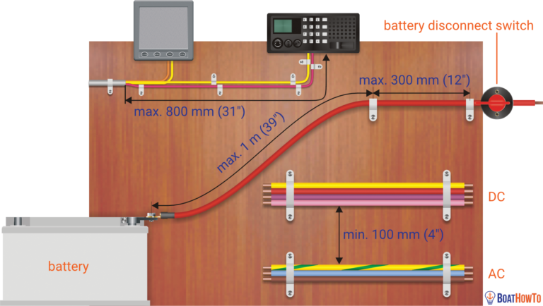
Your boat wiring system should have a marine grade main battery disconnect switch which allows you to open the switch to turn everything off at once. There are some devices on your boat that you do not want to shut off when you turn off the battery switch such as the automatic bilge pump, an automatic fire-fighting system, or propane detector. These will be wired directly to the battery and must be protected with an inline fuse at the beginning of the circuit.
On most boats the ground reference is the engine block which is, in turn, connected to the water via the propeller shaft. Determine if you have a bonding buss for the underwater metals, this is a green wire (or a copper strap) that runs through the length of the boat and connects all of the underwater metals. Although grounding and bonding are frequently referred to interchangeably, a bonding system electrically connects the boat’s underwater metal fittings, such as through-hulls, seacocks, rudders and struts through zincs to protect it from corrosion.
While you are putting together your schematic, make a note of each of the components (ie inverter, charger, generator) with the model number. Then collect all of your Owner’s Manuals, we recommend storing them in an accordion file or binder. While all of this information is available on-line, boaters do not always have access to the internet. The back pages of these manuals typically contain a list of common error messages and resets along with proper installation wiring diagrams. Many boaters include the original bill of sale inside the front cover of the actual manual, which includes a description and date of purchase.
Most yacht clubs, cruising groups or Power Squadrons offer electrical courses either in the evening or on the weekend. For those of you who really want to get to the next step of understanding the what and the why of marine electrical, purchase and read Nigel Calder’s book called “Boatowner’s Mechanical and Electrical Manual”, it is the industry "go to" for marine electrical repair.
A good electrical diagram will save you money because there is nothing more beneficial to a technician or mechanic than an up-to-date schematic. It can save hours of trouble-shooting. As well, the process of spending time with your electrical will help you become more familiar with your boat and get you back on the water faster.
About the author: Jeff Cote is the owner of Pacific Yacht Systems, a full service shop delivering marine electrical and navigation solutions for recreational boats. Visit their website and blog for info and articles on marine electrical systems, projects and more: www.pysystems.ca.
Related Content

Boating Tech Talk Our Marina Only Has 15A Shore Power but I Still Keep Tripping the Breaker?

Boating Tech Talk 3 Bank Battery Charger for 2 Battery Banks?

Boating Tech Talk Can You Explain Battery Combiners, GFCI/ELCI vs. Galvanic Isolators?

Boating Tech Talk Adhesives for Flexible Solar Panels?

Boating Tech Talk Explain Wire Size and Fusing?

Boating Tech Talk AIS Receiver vs. Radar Reflector?

Boating Tech Talk Advice on Selecting an Inverter/Charger?

Boating Tech Talk Common Reasons for Battery Damage?

Boating Tech Talk Advice on Marine Cameras?

Boating Tech Talk How are my Tach and Alternator Related?

Boating Tech Talk Experience with Thermal Cameras?

Boating Tech Talk Automatic Combiner Relay or Voltage Sense Relay

Boating Tech Talk Can You Explain the Difference Between Poly and Mono Solar Panels?

Boating Tech Talk Two Batteries Are Hotter and Need More Refills Than the Other Batteries in the Bank - What Causes This?

Boating Tech Talk What Is The Charging Sweet Spot & Maximum Discharge For My Batteries?

Boating Tech Talk 12V or 24V Thruster?

Boating Tech Talk How Do I Prevent Galvanic Corrosion on My Boat From Boats Around Me?

Boating Tech Talk Gel Battery Rate of Charge?

Boating Tech Talk Advice on Improving Alternator Ouptut?
Boating tech talk help me understand my fuse block.
Copyright © 2024 Pacific Yacht Systems.
Contact Us 604.284.5171
PYS Partners | Privacy Policy


Home » Blog » Boat maintenance & DIY » Learn boat wiring from the experts
Learn boat wiring from the experts
By Author Fiona McGlynn
Posted on Last updated: August 18, 2023
Our review of Boat Electrics 101 , a new online course, co-developed by marine electrics expert, Nigel Calder.
When we bought our 1970s-era sailboat, the boat wiring was a disaster.
We soon discovered a rainbow spaghetti mess of unlabeled electrical wires behind our DC electrical panel. Legacy marine electrical systems from a previous “rewiring” made trouble-shooting and tracing wiring runs exasperating. Lights and pumps regularly failed and we once lost power entirely (despite being on shore power).
In short, living on a poorly wired boat was a nightmare. We needed to learn about our boat’s electrical if we were ever going to go bluewater cruising.

A quick note that this post contains affiliate links (so if you purchase through a link we’ll earn a small commission). We received free access to this course in exchange for a fair and honest review. All the opinions are our own.
Learning how to wire a boat
The good news is that while boat electrical may seem intimidating, it’s actually not all that difficult to get the hang of—but it does have to be done right!
The challenging part was finding a good teacher. We hired an electrician we found on Craigslist to show us the ropes, but this proved to be a complete disaster (with him shorting out the dock mains at our marina and frying our inverter).
After that experience, we resolved to teach ourselves, sorting through the good, bad, (and sometimes, downright dangerous) boat electrical advice available online.
Fortunately, there is now a FAR better way to learn boat wiring…
Boat Electrics 101
Boat Electrics 101 is the online course I desperately wish we’d had at the time. It launched in 2021 and was created by arguably the world’s smartest people on marine electrics including boat systems guru, Nigel Calder.
If you’re not familiar with Nigel, you’ll find his mechanical and electric books in just bout every bluewater cruiser’s library. These guys really know what they’re talking about!

In the course you’ll learn:
- The basics of how electricity works
- Electrical system components and how to safely connect them
- How batteries work (and what you can do to double or triple their lifetime)
- Energy system design: how to balance your energy storage, consumption, and generation
- How to plan a (re)wiring of your boat (including making your own boat wiring diagram)
Unlike my grade 10 science teacher, the course does a great job of taking an important concept and breaking it down with animations, diagrams, and videos.
For example, In one module, Calder demonstrates the importance of circuit breakers by driving a screw through an unprotected wire. The cable immediately went up in flames, filling the room with smoke! Lesson learned.
Best of all, all of their materials follow ABYC and ISO standards. Both Nigel and Michael have been members of American Boat and Yacht Council (ABYC) and the International Organization for Standardization (ISO) committees, so they know the rules and best practices better than anyone.
I’ve taken Boat Electrics 101 and can’t say enough good things about it. If you sign up now, you can take advantage of their early bird offer ($199) and save $100 . Oh, and you keep your access to the course forever (even as they add new material). Even if it saves you hiring a marine electrician just once, the course more than pays for itself.
The rewards of doing it yourself
Learning how to wire a boat was not only rewarding but it made us more capable, self-sufficient boat owners. It’s an essential skill for people with older boats, but even new boat owners will find there comes a day when an electrical component fails or they want to add more bells and whistles.
We’ve saved a lot of money by doing our own marine electrical work (not to mention avoided days stuck in port waiting for a professional marine electrician). So, don’t let marine wiring intimidate you. With the right knowledge and tools, you’ll be well on your way to doing your own marine electrical.

Fiona McGlynn is an award-winning boating writer who created Waterborne as a place to learn about living aboard and traveling the world by sailboat. She has written for boating magazines including BoatUS, SAIL, Cruising World, and Good Old Boat. She’s also a contributing editor at Good Old Boat and BoatUS Magazine. In 2017, Fiona and her husband completed a 3-year, 13,000-mile voyage from Vancouver to Mexico to Australia on their 35-foot sailboat.
Sunday 23rd of January 2022
I learned the hard way about boat electrics when locked onto the engine block and a battery charger on a sailboat connected to shore power with a faulty ground. I was being tazered by 240v.
My friend saved my life by pushing me off the engine with a broom handle!
Yes, understanding boat electrics is something that is as important as navigation!
Oh my gosh, that sounds terrifying! What a nightmare. I'm glad you're okay. That was some good quick thinking on your friend's part!
Terms and Conditions - Privacy Policy

14 Steps To Wiring Your Boat
What you need to know to install or re-wire the electrical system on your boat. a step-by-step practical guide. covers planning, diagrams, wiring, batteries, over current protection and more..
I want to thank Ed Sherman for reviewing this page for accuracy.
A question often asked on boating and boat building forums, and by visitors to my web site, is: “I need a simple wiring diagram for a small outboard boat to wire up the lights and few other things, but no one seems to have one. Is there one, and where can I find it? Are there a set of step-by-step instructions?”
There are wiring diagrams, websites and forums that tell you how to wire an electrical system for large boats and bigger sailboats. But when it comes to small boats there is a distinct lack of information and diagrams for how to install a simple, safe, and reliable electrical system.
The following is meant to apply only to small outboard boats under 16 feet with 50 or 60 horsepower or less. It can be applied to slightly larger boats that have a simple 12V DC system using one or two 12V batteries.
Note 1 : I will not deal with the wiring specifically for the outboard motor and controls. Here is a web site where you can obtain wiring diagrams for most outboard motors. Most new outboards come with a wiring harness and a manual that has wiring diagrams. See Master Tech Marine Outboard Wiring Diagrams .
Note 2: If you are re-wiring a boat with an electrical system installed: Don't rip out that old system yet ! Use the old system to help make a plan in steps 1 through 7. Trace out each wire and put that on your diagram. This will make it far easier to locate wires and equipment. Wait until you actually start installing wiring in step 12. Then replace each set of wires with new. This may take a little more time, but will result in far fewer mistakes and less troubleshooting.
Note 3: Throughout this I will give references to the US Code of Federal Regulations (CFR) requirements that apply to boat manufacturers, and to the American Boat and Yacht Council industry standards. Examples: 33 CFR 183.401, or ABYC E-11. The US Coast Guard Regulations (the CFR) and the ABYC standards are good guidelines to follow for a safe and reliable electrical system. They are used by marine electricians, professional boatbuilders, designers, marine surveyors, and marine repairers. If that’s how the pros do it, so should you.
Step 1. Make a Plan. Decide what you want to install, and where it will go. See Electrical Planning
Step 2. Draw a simple electrical schematic (diagram) that shows each piece of equipment, the fuses, switches, and how all of this will be connected. This is not a diagram of where the equipment is located on the boat. That will come in Step 8. It is simply a diagram of the electrical circuits. Here are two alternative examples. (Click on the diagram to expand.) The first diagram uses a positive buss bar. The second omits the positive buss bar. For clarity I did not use color codes except red (positive) and black (negative).
Do not be concerned if you don’t know electrical symbols. Just make a box or circle and write in what it is, or you can use a picture of the item. As long as you understand what goes where, and how they are connected, it’s Ok. Remember, any 12V DC device must have at least a positive and negative wire connected to it. Put a plus or minus next to the wire or use red for positive and black for negative. On metal boats do not use the hull as a return (negative) path. Connecting your electrical system to a metal hull can result in stray current corrosion.
See also BoatUS diagram:
There are several ways to draw wiring diagrams. The most important thing is that you understand what you are diagraming. It needs to be simple enough and clear enough for you to be able to refer to it in the future and still understand what each item is, what the wiring is and how each item of equipment is connected to the electrical system. That way, in the future if you want to add or subtract equipment you can do so by referring to your diagram and determining where and how the new item fits into the system.
Step 3. Batteries: Decide where you will put the battery. Later we will decide the capacity and type of battery but for now we only need to decide where to put it.
The battery is the source of power for starting, instrumentation, and lighting. There may be a second battery on some boats for running a trolling motor or other equipment.
Batteries should not be too close to anything that can cause an accidental short. There should be 12 inches of space all around them. Batteries must not be directly under or over fuel lines or under other electrical equipment such as a charger or inverter. If they are, there must be a floor or panel separating them. ABYC E-10.7.5 and 10.7.6 Storage Batteries
Batteries need to be in a space that is ventilated to the atmosphere. 33 CFR 183.420(e) This applies to all batteries, not just lead/acid batteries.
Batteries must not move, so they have to be fastened down. 33 CFR 183.420(a)
There should be a tray under a battery for spilled electrolyte, or it should be in a battery box, and fastened down so it won’t move under any conditions. (ABYC E-10.7.2) The Coast Guard does not require a tray or a battery box but ABYC does require some means to contain spills. If it is strapped down in a tray, spilled acid won’t damage the boat and the battery won’t move. The terminals need to be covered with a boot or some other device that protects them from accidental contact with metal tools. But, if the battery is in a box the terminals are protected against accidental contact with tools, spills are contained, and it won’t move.
The battery should be close to the engine. Since starting current is so high, and the wires to the starter are not fused, you want to keep the wires as short as is practical.
The battery should be a combo starting/deep cycle battery, usually sold as a marine battery. An auto battery would do for starting and lights. But, for running a radio, and other electronics while anchored or fishing, a battery with a little deep cycle capacity is needed so the battery doesn’t go flat and leave you stranded when you try to restart the engine.
How big a battery (capacity, not physical size) do you need? That depends on the amount of load on the battery. I will show how to determine that in Step 12.
There is one non-electrical consideration; weight. Lead acid batteries can weigh up to 50 lb. Think about how the weight of the battery will affect weight distribution on your boat, especially if it is on the same side as the helm and controls. You may have to move it to balance the boat side to side. If you have a very low transom, how will the weight of the battery affect the water line at the transom?
Step 4. Battery Switch: Some people think that a battery switch is not necessary on a small boat. I think a battery switch is necessary to turn everything off when you are not using the boat.
Where the battery is located determines where the battery switch goes. It should be close to the battery but easily accessible to be switched off in an emergency. ABYC E-11.6.2.
A good brand is Perko but there are others. Avoid any battery switch that is not UL Marine Listed. There are cheap ones on the market that are not UL listed and can get hot and melt.
A battery switch must be ignition protected. (33 CFR 183.410)
Ignition protection means that it will not ignite gas fumes if they are present. This is extremely important if you have a gasoline fuel tank in the same compartment as the battery.
Use only ignition protected electrical components. You don't want anything in there that will set fuel vapors off. Batteries are not considered a source of ignition because there are no moving parts, but if you make accidental contact with metal tools it can create an arc. So, the terminals must be protected, and battery switches and other electrical equipment in this compartment must be ignition protected.
Buy a switch that has a provision for two batteries because you may want to add a battery in the future. The switch will have three positions. OFF, 1, 2, and BOTH. The 1 position connects the one battery and allows charging of that battery when the engine is running (if your outboard is large enough to have an alternator). The 2 position connects and charges the second battery, if there is one, and the BOTH position puts the two batteries in parallel doubling the battery capacity and charging both at the same time. You won’t need the BOTH and 2 positions now, but this gives you the option to add a second battery.
Step 5. Fuses: Next, install a fuse block close to the battery switch. Fuses must be within seven inches of the source of power (33 CFR 183.455) but you can go up to forty inches if the wire is sheathed. Standard wire loom is fine as a sheath. Be aware, the fuse is there to protect the wire, not the equipment. If you overload wiring it gets hot, melts and starts a fire. We will determine the size of the fuse later. See Step 12. Buy a fuse block with two fuse holders. That way you have a spare if the fuse blows. This is generally a good idea. When installing fuse blocks get ones with more fuse holders than you think you need. You will need them eventually. One or two extra fuse holders is good.
Step 6. Equipment Location: Determine where each piece of equipment will be.
Think about where you want things to go. Depth finders need to be where they are easy to see, but not blocking your vision when operating the boat. Radios should be where they can be easily reached, and for VHF, reach the mike. The back of the console or surface you are mounting them on needs to be easily accessible for access to the wiring.
Step 7 . Locate the fuses, buss bars and switch panels.
Decide where to put fuse boxes, buss bars, switch panels, etc. Each of these must be close to the equipment they power, and easily accessible to be worked on. They cannot be hidden behind equipment or inaccessible panels. This may sound obvious, but I have seen some very bad installations. Also, they should be protected from spray or rain.
Most electrical and electronic equipment comes with pigtails. Pigtails are wires coming out of the equipment and may only be a few inches to several feet long. Sometimes they have a connector attached to the ends of the wire. When determining where stuff goes consider the length of the pigtails, because you don’t want a rat’s nest of wires hanging loose.
Switch boxes: A box or panel where switches can be mounted to control stuff. On a small outboard boat this is usually the dash or the console.
Fuse block: A panel with fuse sockets on it. It can be open or covered.
Buss bar: A block with studs for connecting wires.
Typical Buss Bar: This buss bar is for the negative wires. The large wire on the left is the battery negative.
There are some devices that are connected directly to the source of power and do not go through fuse blocks and switches. They need to always have power. One is the bilge pump. Bilge pumps may have a float switch that automatically turns the pump on when water in the bilge gets to a preset height. This won’t work if the pump is not wired directly to the battery. It is not good practice to wire it directly to the battery though. Wire it to the power input side of the battery switch. It is good to install a switch at the helm that turns the pump on manually.
If your boat has an anchor light, you may also want to wire the switch for the light directly to the power input side of the battery switch. That way you can turn on the anchor light when the battery switch is off.
Step 8. Make a diagram of the boat showing where the wiring, equipment and fuse blocks will be located.
Make a rough drawing of the boat looking down from the top. This is called a general arrangement and shows how the boat is laid out. Using your electrical schematic, put in where the equipment, fuse boxes, buss bars, switch boxes and wiring are going to go. Check this against the actual boat to make sure you aren’t missing something.
Wiring cannot go through pieces of equipment, pipes, tubes, and other solid objects. They can go through walls and bulkheads and panels. Wiring must be easily accessible for installation, trouble shooting and replacement. It must be fastened down at least every 18 inches (ABYC 11.15.4.1.9) so it isn’t or chafing on something. Where wiring goes through a bulkhead, wall or panel, it must have a grommet or padding to protect the wire. 33 CFR 183.445(a)
Your diagram may look something like this; (Click on image to expand)

Step 9. Wiring: Figure out how much wire you need, what size wire you need, and what color it should be. Wire standards.
What about the wires from the battery Switch to the starter? The wire needs to be a very heavy gauge, at least a 4 AWG on small outboard boats, because starters draw a lot of current. Both the positive and negative wires should be the same size. If the outboard has the wires for the starter already installed, the wires from the battery to the switch should be the same size as those wires. The engine manufacturer has determined the amount of amperage the starter draws and correctly sized the wires for the load.
The positive wire (red) goes from the battery to the input side of the battery switch. The negative (black) wire goes to a buss bar. One post on the buss is for the wire from battery to the engine block (ground). Another wire goes from the buss up forward to the dash. The others are for other equipment. There should be as many terminal posts as you need plus a few extra.
Color Codes: The positive wire should be red. Negative can be black, or yellow, or black with a yellow stripe. Throughout the boat negative wires should be black or yellow or a combination. AT the dash or console, all positive wires from the fuse block to the instruments and the equipment, should be color coded using the standard color codes for marine wiring. Direct Current Color Codes: From ABYC E-11.15.2.3 Table 11 and Table 12.
Direct Current Color Codes: From ABYC E-11.15.2.3 Table 11 and Table 12.
Color codes tell you what the wire is for. But label the wire on both ends. A simple piece of tape with a name written on it will do. They do not need to be fancy labels, but if you prefer, you can buy labels at electrical suppliers or hardware stores.
Wire must be marine wire. (33 CFR Sec. 183.435) Do not use auto wire. It is not made to the same standards as marine. Most marine wire is labeled UL 1426. It must be copper stranded wire. It does not have to be tinned, although tinned wire will last longer. On a small boat it is not necessary. Do not scrimp on wire though! Cheap wire could mean the difference between a reliable system and one that you constantly have trouble with. Buy good quality wire. I have seen 100 ft spools of Ancor 16 AWG Tinned Marine Wire for sale on-line for as little as $24.00 USD.
What size wire? American Wire Gauge (AWG) is in reverse order. The larger the number, the thinner the wire. The thickest wires are 00 or 0 AWG. The smallest gauge allowed on boats for a single wire is 16 AWG, or 18 AWG if it’s in a bundle or sheath (33CFR 183.425), but this may be way too thin for the equipment or the length of the wire run. The only exception to this is wire inside electronic devices or part of the electronic controls on the engine. 33 CFR 183.425(g)
The thicker a wire is, the less resistance it has. The longer a wire is the more resistance it has, and so there is a larger voltage drop. You want to minimize the resistance and the voltage drop. So you first need to figure out the wire size based on how many amps are being used, and then by how long the wire is. Use the tables in Appendix A, at the end of this page, to determine the correct size. Don't just guess at wire size and buy larger diameter wire such as 14 or 12 AWG. See Wire Size:
For the purpose of determining wire size, the fuse block the wire is coming from is considered the source of power. For the wires running from the battery to the starter, or to the under-dash fuse block, the battery is the source of power. In the two examples below the fuse block under the dash or console is the source of power.
Here is an example:
A Hummingbird Model 345C depth sounder draws 380ma (milliamps from the specifications). The installation includes a 6 foot power cable of 18 AWG wire. This may be fine for connecting it to a fuse block near the dash. But we need to size the cable running from the battery to the dash. It is going to be at least 10-12 feet long on a 16 foot boat. Double that length for the negative return wire.
Use table 3 in The Appendix for voltage drop. Most boat manufactures use wire rated for 105C (degrees Celsius - the temperature rating of the insulation on the wire). Looking at the table under the column for 105C we see amperages starting at 20 amps, 25 amps, 30 amps, and so on. Following the row for 20 amps to the left column we find 18 AWG.
From the table on voltage drop an 18 AWG wire 20-24 feet long (30 feet in the table) with a 15-ampere load will have less than a 10% voltage drop. But it can only be 18 if it’s in a sheath or bundle. So go up one size to 16 AWG.
Another Example:
Suppose I have three electronics running off a fuse block in the dash or console. Each piece of equipment requires 1 amp at 12 volts to run. The total amperage for the three items is 3 amps. From the fuse block in the dash or console to each item of equipment, there is a positive wire from the fuse to the equipment, and a negative wire running back to the buss. Using 1 ampere, we determine the size the wire should be, by using table 1 and 3 in Appendix A. For instance, if the positive wire is two feet long then the total length of positive and negative wires is 4 feet. Looking at the Table 1, the line for 18 AWG wire at 105C allows up to 20 amps.
So, we could use 18 AWG. Look at Table 3. We see that an 18 AWG wire, 10 feet long, will have less than a 10% voltage drop for up to 5 amperes. Again, we could use 18 AWG but since 18 AWG wire has to be in a bundle or a sheath we add a level of safety by using 16 AWG.
This is done using the tables developed by the US Coast Guard and ABYC. You don’t have to know any formulas to figure it out. The first table determines the wire size based on the load in amps and the second table the size depending on length and voltage drop. You use the larger wire if there is a difference.
See the table in Appendix A at the bottom of this page. or ELECTRICAL TABLE: 33 CFR 183.42: ALLOWABLE AMPERAGE OF CONDUCTORS FOR UNDER 50 VOLTS or: ELECTRICAL SYSTEMS VOLTAGE DROP
Step 10. Wiring tools. Wire connections (terminals). See Connectors :
Tools: Use good quality tools, especially good quality crimpers and wire strippers. Cheap crimpers make bad crimps. Bad crimps make bad connections. Poor wire strippers nick the metal conductor which may cause the wire to break or have a high resistance. See My Page on Practical:
Wire terminals must be used . Connections should never be a bare wire wrapped around a stud or post. This is bad practice, and can easily come loose or result in a high resistance connection. High resistance equals heat, which results in fire. Never use wire nuts to connect wires on a boat! They are prone to vibration and corrosion. ABYC E-11.15.3.7 Twist-on connectors (i.e., wire nuts) shall not be used.
Use crimp type ring or captive spade terminals. Captive spade terminals have a tang on the ends. This prevents them from being pulled off or slipping off the stud or post. Connections must resist being pulled off. In the ABYC wire standard there is a table listing how much of a pull they must withstand depending on the size of the wire. A 16 AWG wire must withstand a ten lb. pull. A 4 AWG wire must withstand a 70lb pull.
You can solder connections if you like but crimp them first . ABYC standards do not prohibit soldering, but they do not allow soldering to be the sole source of support for the connection. (ABYC E-11.5.3.8) This is because solder creates a hard spot in the wire which is not as flexible as the wire itself and not as resistant to flexing and vibration. So, if you solder you must also crimp. Crimp first, then solder.
Seal wire connections with a good waterproof sealant , usually marketed as dielectric grease. There is no requirement to do this, but it prevents water from getting in the connection and wicking up the inside of the wire insulation or corroding the connector.
My method. I do not solder. First I slide a short length of heat shrink tubing onto the wire. https://en.wikipedia.org/wiki/Heat-shrink_tubing How long it is depends on the wire and connector size. Usually if the tubing extends about 1/2 inch (1 centimeter) beyond the end of the connector, that is enough. Then I use dielectric grease. See Wikipedia on Dielectric grease . Dielectric grease is non-conductive grease, usually silicone that is also waterproof and can be used to seal connectors. Before crimping the wire in the connector, I squirt a little dielectric grease into the connector where the wire goes. I then insert the wire and crimp it. Then I slide the tubing down over the connector and shrink it with a heat gun or hair drier so it seals itself around the wire and connector. The combination of grease and heat shrink tubing should keep the water out.
Heat Shrink Tubing And Connectors, AAA protection, How to install and repair. http://youtu.be/jCRsx38WRw8
How to get a good crimp: Marine How to: Wire terminations: https://marinehowto.com/marine-wire-termination/
Step 11. Fuses . How big should your fuses be?
Fuses are rated by amperage and protect the wire from overheating and fire. Fuses must be rated at the same or less rating of the wire. If you have a wire that is rated at 15 amps you need a 15 amp fuse. Each circuit is rated for a certain amperage, such as 15 amps or 20 amps, and more equipment is not added to the circuit if it would cause it to draw more current than the fuse is rated for.
This can become an issue on little boats too if you have more equipment, or something like a powerful stereo system that draws a lot of amperage. Then it should have its own circuit and its own fuse for the circuit.
The question is how many fuses in the block? That depends on how much stuff you are running. I would have a fuse for the lights, one for the instrumentation, and one for any electronic devices, plus a spare. That is four. But for expansion maybe a six or 8 fuse block would be better. Again, in the future you won’t have to buy a new block. See Overcurrent Protection:
Step 12. Installing equipment .
Start with the battery, the battery switch, and the main fuse block.
Selecting a Battery: Batteries are rated by voltage and capacity. We are using a 12V battery. There are two ratings, CCA and MCA See Batteries at:
CCA Means Cold Cranking Amps. MCA means Marine Cranking Amps. These are measures of how many amps the battery can deliver for 30 seconds and maintain the voltage at 12V. Basically the higher the CCA rating the longer the battery will maintain its voltage. Batteries are also rated by amp-hours. 1 amp for 1 hour is 1 amp-hr. Generally the rating is based on how many amps the battery will discharge for 20 hours until the charge drops to 10.5 volts. The higher the amp hour rating, the longer the battery will power your equipment. Also, batteries are rated for Reserve Capacity which is how many minutes it will deliver the same voltage at 80 degrees. An average marine battery should have a Reserve Capacity of 60 to 90 minutes. Anything less is not adequate.
There are four types of batteries commonly used on boats, Wet Cell (also called lead acid, flooded, or flooded lead acid, and sometimes abbreviated FLA), AGM (Absorbed Glass Mat, Gel, and Lithium, but for now I’ll stick with the standard wet-cell battery. They are relatively inexpensive, can be purchased anywhere, and for a small boat, more than adequate. A battery with a CCA or MCA rating of 200-300 should do but we’ll determine that when we calculate the loads. See table below on how to calculate loads. Battery Capacity should be at least twice the load.
To calculate loads, list the equipment you are planning on installing. In the chart below the following items are listed. Navigation lights Bilge Pump Radio (Only when receiving) Depth Sounder engine electrical Instruments GPS Bait well pump Horn Radio TX. (VHF Marine radio. It draws more when transmitting)
Determine from the specifications for each item what the current load is in amps. Separate them into continuous loads (on all the time) and intermittent loads (only on when used). Determine how many hours they will be used. Multiply the amps times the hours to get amp hours. Add up the amp hours.
See Also Electrical Planning
Double the result to determine what the rating of the battery should be. For this case, 200.
Another consideration is the battery group size. Batteries come in different physical sizes. A Group 24 battery is 10 ¼ inches by 6 13/16 inches by 8 7/8 inches. A Group 27 battery is 12 1/6 inches by 6 13/16 by 8 7/8 inches. The physical size is determined mainly by how much space you have for the battery and its weight. A bigger battery weighs more. A large group size does not necessarily mean it will last longer. That is determined by the battery ratings for amp hours and reserve capacity. The most commonly used size on small boats is Group 27.
Install the battery box if you are using one, or a tray, then the battery. Now that you have installed a battery you can begin installing equipment. Install lights and electronic equipment. You want everything in place before you begin wiring. Put in switch panels and fuse blocks.
From Step 5. We need to determine the size of the main fuse at the battery. The continuous loads add up to 10.5 amps. The fuse in a DC circuit should be about 150% of the load so a 15 amp would be appropriate. (ABYC E-11.10.1.5.)
The fuses for each circuit of our example should be at least 3 amps except for the VHF radio because on transmit it draws 6 amps. So, use a 10 amp fuse for the radio circuit. Check the manufacturer's installation instructions for recommended fuse sizes for each piece of equipment. Remember, this fuse is to protect the wire to the equipment, not the equipment. Some equipment may have built in or in-line fuses for that purpose.
Step 13. Installing Wire:
Begin installing wire, starting at the battery and working outward to each fuse block and buss bar, and then on to each piece of equipment. Remember to follow the color codes and label the wires on both ends. If you decide to make any variations from your diagrams make sure you change the diagram for future reference.
Step 14. Turn on the power. Test by turning on each item, one at a time, to see if it works. Troubleshoot as you go. If there is a problem, fix it before you proceed. Once everything has been tested individually, turn on everything, one at a time, until everything is on. If a fuse blows or something doesn’t work the last item you turned on is where the problem lies. Turn everything off, fix it and then try again from the beginning.
An Excellent Article: Avoiding Boat Electrical Mistakes by Ed Sherman; Boat US Magazine https://www.boatus.com/expert-advice/expert-advice-archive/2016/august/avoiding-boat-electrical-mistakes
An excellent article by Owen Youngblood on Wiring Your Boat , from the Metal Boat Quarterly
How to Wire A Boat from New Wire Marine https://newwiremarine.com/how-to/wiring-a-boat/
The USCG Boat Builders Handbook for Electrical Systems is available on-line at https://safeafloat.com/wp-content/uploads/2021/04/I-Electrical-Systems-Final-4-14.pdf
Contact ABYC for a copy of E-11, AC and DC Electrical Systems on Boats. There is a fee. See: https://abycinc.org
Appendix A: Allowable Amperage and Voltage Drop Tables
Note: This is the table that is in the Federal Regulations. The Federal Regulation now uses the ABYC table. It is published in 33 CFR Subpart I sec 183.425. ABYC Standard E-11 has five separate tables based on how many conductors are in a wire bundle.
The table for voltage drop is below. This is only for 12V DC. Contact ABYC for a copy of E-11, AC and DC Electrical Systems on Boats. There is a fee. See: https://abycinc.org
This is the table to determine wire size due to voltage drop based on the length of the wire. This table is for 12 volts only. The top row is the length of the wire in feet. The first column below Total Amps, is the amount of maximum amperage. The number in the row to the right of the total Amps column, is the size of the wire for a 10% or less voltage drop. Example: 25 feet of wire (top row) at 15 amps (first column) the wire would be 14 AWG.
Navigation Lights: I added this section because many people asked for it.
Wiring Navigation Lights for boats with combination red/green bow lights and an anchor/sternlight on a pole. I have been asked many times if there is a standard wiring diagram for hooking up the lights on a small outboard or inboard boat. There are some variations on this but here is how I did it on my boat.
The below diagram is for small boats with a red/green combo light on the bow, and a single sternlight that can also be used as an anchor light. Usually these have a single switch with 3 positions; Off, 1. anchor light, 2. combo bow light, sternlight/anchor light, and instrument lights. The diagram shows a Cole-Hersee switch that is in common use, but there are other manufacturers that also make switches for this, such as BEM and Blue Seas. They all serve the same function. In this diagram the lights are wired directly to the battery. However, some people prefer to wire it through the battery switch so the battery is not discharged if the lights are accidentally left on. It is just a matter of switching the power wire from B on the lights switch, to the number one position on the battery switch.

© newboatbuilders.com 2007 All rights reserved. revised 03/17/2023
Created with Dreamweaver 21.2 ©newboatbuilders.com 2022 All Rights Reserved
Are Your Boat Electrics
Safe & reliable, ...or do they look like this:.
- Your boat's electrics are a "black box" to you?
- You are worried that parts of your system might fail?
- You want to upgrade or install new equipment in a professional manner?
Sounds familiar?
We teach you how to install and maintain a dc system on a boat like a pro, boat electrics 101 , safe & reliable dc systems, your teachers.

Nigel Calder

Dr. Jan C. Athenstädt

Michael Herrmann
We are Nigel, Jan & Michael. We help you understand, extend, and redo your boat electrics. The right way.
I now understand all the electrical systems and how everything works together.
Bob russell - s/v spartina.
Jan, Nigel & Michael, I want to let you know how impressed I was with the BoatHowTo course !! Having purchased a new to me Island Packet 350 this year, I was overwhelmed with all electrical systems on the boat! Modern cursing boats have become very complex and I was lost! Having taken your Boat Electrics 101 course I now understand all the electrical systems and how everything works together . From the very basics, through creating a detailed circuit diagrams of the electrical systems on my boat, my knowledge is years ahead of where I thought it would be at this point. Thanks for a wonderful, extremely useful (and fun) course that takes a lot of the mystery out of sailboat electrical systems!!
Boat electrics is not rocket science ... ...but it still has to be DONE RIGHT !
Electrical systems on boats have become more and more complex over recent years.
Even moderately equipped boats today rely completely on their electrical system . A loss of power means in most cases an emergency at sea. (Or do you still have a sextant and all nautical almanacs on board?)

Boat electrics are often poorly understood, despite being such a vital part of the operation of a boat.
The good news: It's not that hard!
With a bit of time and a commitment to learning, everybody who mastered basic high-school math and physics will be able to understand the DC system on a boat. All it takes is a reliable and easy to understand source of information .
You want to understand your system?
Clearly expressed and illustrated, the course is full of practical information, derek nowek - falmouth, me.
The Boat Electrics 101 course is a fantastic resource for beginners like myself who know little about electricity and even less about boats electrical systems. Clearly expressed and illustrated, the course is full of practical information presented in a way that makes boat electrical systems understandable. Thank you for putting it together.
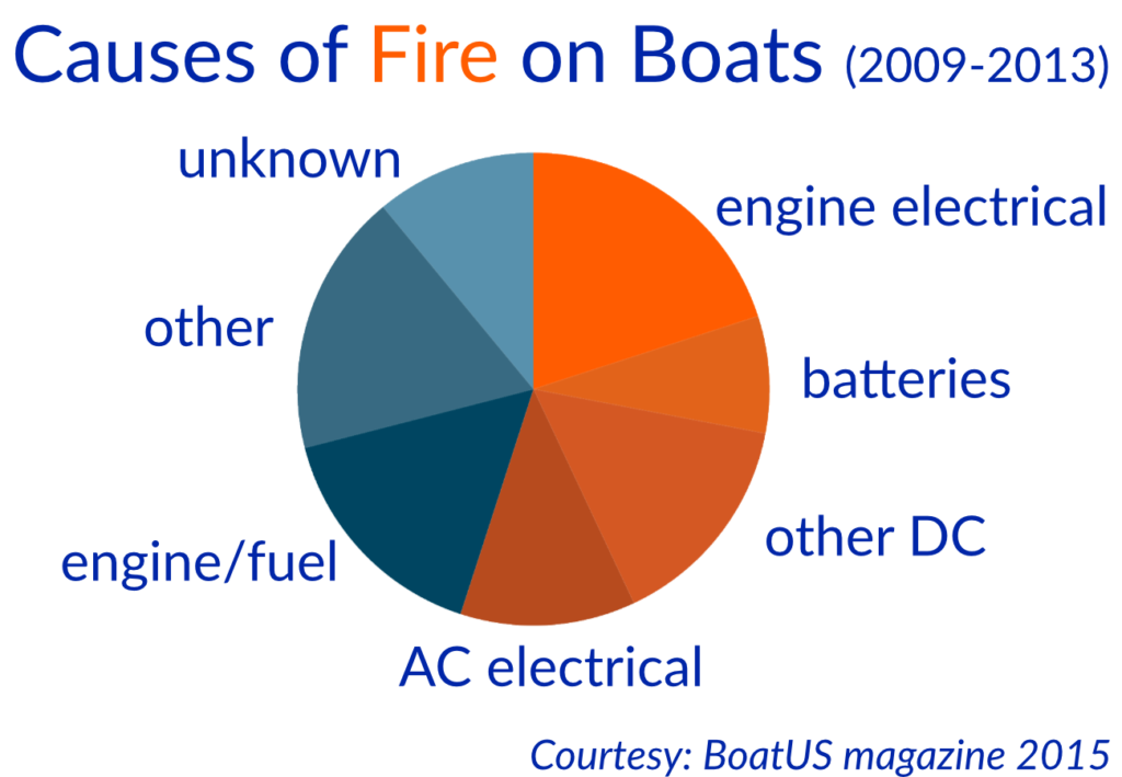
The majority of fires that start on boats are caused by the electrical system !

Understanding your boat's DC system can significantly improve the safety of your boat!
Unfortunately, many owners have only a vague understanding of their boat's electrical system. Or, even worse: They think they know how to install a system and end up making damaging mistakes...
...and teach others these mistakes in blogs or on YouTube.

YouTube is full of videos about Boat Electrics
– many are wrong and some are dangerous.
The internet is a great source of information. And in recent years, many people have shared their experience installing or fixing electrical problems on their boats.
The problem: Many of those people are not professionals!
It's easy to put a professionally looking video on YouTube...
...but it is hard to tell, if this actually is professional advice - or misleading BS.
If you follow bad advice on how to varnish teak and you end up with a mess, in the worst case you lose time and a bit of money.
If you follow bad advice on how to connect batteries and your boat ends up in flames, this is a different story.

A typical example of bad advice...

...is soldering. Soldering is often praised as a great way of connecting wires. On a boat, it is not. Soldered connections are rigid and tend to break when exposed to the vibrations common on boats.
This is why electrical installation standards from the American Boat and Yacht Council (ABYC) and the European International Organization for Standardization (ISO) both explicitly prohibit soldering as the only means of connection!
You want know how to do it right?
Your brand new boat is properly wired..., ...or maybe not.
When visiting boat shows, Nigel likes to inspect the electrical systems on brand new boats . Unfortunately, this has become quite frustrating: a shockingly high number of production boats come with badly installed electrics – straight from the boatyard.

These batteries were installed on a brand new boat. What's wrong here?
- Inadequate support against sliding off the shelf
- Parallel connections badly designed - this will lead to premature battery death
- Too many cables on the positive battery post
- No overcurrent protection devices anywhere near the positive battery pole
This installation might look neat at first glance. But:
It is unprofessional and asking for trouble!
You want to assess your system, i now feel empowered to research and undertake this work on my own., mark sweetnam - ireland.
Wow, what an outstanding course – thank you so much. I intensively studied each lesson, took notes (frequently pausing the video to do so), read and made sure I fully understood the lecture notes and then likewise all comments. The entire course took me about 6 full days to complete. In my own case I have owned a 30 year old Swedish boat (Najad) for the past 10 years. It has both 12V and 24V house systems, with two alternators. I got the batteries replaced about 8 years ago (with Victron AGM) but am now looking to upgrade the electrics in numerous ways, and obviously to audit and rectify any OCP or other shortcomings. New batteries will obviously be needed shortly but I also want to add solar. But mainly I want to either get rid of the 12V bank (and use DC-DC converters for the 12V house load) or add 12V-24V-B2B charging both for redundancy and to use full capacity of both 12V and 24V alternators and shore power battery chargers. I now feel empowered to research and undertake this work on my own. Thanks again.
Who or what are ABYC and ISO ?
The ABYC E-11 and the ISO 13297 standards cover the principal electrical systems on small craft.
Even though they are legally non-binding, they are based on decades of experience of hundreds of experts in the field.
So, instead of trying to figure things out for yourself (with potentially disastrous consequences), it is a good idea to follow these standards as closely as possible.

All three of us are members of various standards committees of the ABYC and ISO, Nigel and Michael for decades. Everything we teach at B OAT H OW T O is compliant with ABYC and ISO standards.
There is no one who knows the standards better than us.
The American Boat & Yacht Council (ABYC) is a non-profit, member organization that develops voluntary global safety standards for the design, construction, maintenance, and repair of recreational boats. As an independent consensus-based body, the industry experts at the ABYC (including Nigel Calder from B OAT H OW T O ) work together with the sole purpose of protecting the safety of the boating public.
The ABYC’s Standards and Technical Information Reports for Small Craft cover all major boat systems. The development and regular review of these standards provide boat building guidelines that correlate directly with a significant reduction in the number of boating accidents over the past six decades.
The International Organization for Standardization (ISO) develops high quality voluntary International Standards. The sub-group of the ISO that addresses small craft (up to 24m/70 feet), is known as Technical Committee (TC)188 (of which Michael Herrmann and Jan Athenstädt from B OAT H OW T O are both members). This committee has developed a set of standards that are closely aligned with the ABYC standards.
With respect to boat electrical systems the principal difference between the ABYC and ISO standards lies in the fact that the ABYC standards tend to be more detailed. In order to provide the most detailed information in our lessons, we follow the ABYC standards. Where there are minor disagreements with the ISO (only a handful) we point these out.
You want your electrics to comply with ISO & ABYC standards?
We know what we are talking about..., ...and how to apply this knowledge..
Understand the basics of a safe and troublefree installation. Learn how to plan and design a system. Get practical advice on how to put everything in place.
Understand the basics of electrics in general and boat electrics in particular
Learn how to assess existing systems and how to (re-)design the wiring of your boat
Get your hands dirty with practical advice on how to crimp wires, install batteries and much more
The course has given me the knowledge to make better choices
Tommy kaine - sv alboe.
Just a note to say how terrific the Boat Electronics 101 course is. It is very comprehensive. It has empowered me to refit my 1976 Westsail 32 original electrical system. Though I am outsourcing some of the work, the course has given me the knowledge to make better choices, do my portion of the project, and have a smart conversation with the contractors. Thanks for all your hard work and keep it up!
Good marine electricians are rare...
...and expensive, so why not learn how to do it yourself.
Instead of paying hundreds of dollars for a few hours of advice and help from a marine electrician, you can invest in your knowledge - and become more self-reliant!
With our help you can learn how to operate, maintain and extend your boat's electrical system in a professional manner. Better than many people who do this for a living!

Invest in your knowledge and self reliance
Even if you know a good marine electrician: You will still have to deal with problems on your own as soon as you are away from the dock.
Proper preparation is key to good seamanship.
Stop worrying about potential hidden failures in your system. Empower yourself by uncovering the secrets of your boat's electrical system. Regain control in the complex world of marine electrics.
B OAT H OW T O helps you spend a carefree and relaxed time on the water. Boating or sailing the way it's meant to be.
Join us for our ONLINE COURSE on DC Systems:
B oat h ow t o boat electrics 101.
Set up a safe and reliable DC system on your boat that complies with ABYC and ISO standards.
- 1 Fundamentals: Understand the basics of electricity, how common components work and how to connect them.
- 2 Batteries & Charging: How do lead-acid batteries work and how to charge them to double or triple their lifetime?
- 3 System Design: Step-by-Step guide to plan and install a DC-System on your boat.
In 8 modules (plus bonus lessons & videos), you will learn everything from the basics of electricity to designing a whole DC system on your own.

Boat Electrics 101 - Course Contents
59 easy to follow video lessons will turn you from beginner to expert. .
Take a look at the course syllabus:
Introduction
About Boat Electrics 101
A quick welcome and introduction of your teachers and a few words on who this course is for and what to expect.
Course Structure & Overview
Get an overview on the contents of this course and the underlying standards.
Safety Precautions
In this lesson we will cover some dangers and necessary safety precautions to keep in mind before working on your system.
Electricity
Get to know the basics of electricity and learn about Volts, Amps, Ohms and how they relate to each other.
What is electricity?
What is electricity and what happens when a current flows? We take a quick look at the behavior of electrons inside metallic conductors.
Voltage, Current & Resistance
Learn all you need to know about voltage, the equivalent to pressure in electrical systems.
Ohm's law allows you to calculate how resistance affects voltage given a certain current and vice versa.
Power, Energy, Consumption & Capacity
Power the product of voltage and current. With two examples you will learn how to calculate the power draw of an appliance.
A quick recap on everything we have learned so far.
End-of-Module Quiz
Test your knowledge with a quiz!
Electrical Components and Circuit diagrams
Get to know the most common components of a boat's electrical system and learn how they can be represented in a circuit diagram.
The Idea Behind a Circuit Diagram
Learn why it is important to be able to read and draw circuit diagrams.
Wires & Conductors
In this lesson you learn the symbols for wires and conductors and and their connections.
Circuit Ground
What is ground/earth and how is it represented in circuit diagrams?
Switches, Buttons & Relays
Get to know the basic symbols for switches and buttons and learn how relays and solenoids work.
Resistors & Shunts
Get to know the symbols for resistors and learn about the most common type of resistor on board: the shunt.
Fuses & Circuit Breakers
How are fuses and circuit breakers represented in circuit diagrams?
Coils & Transformers
Coils mostly occur on boats within transformers. Here you will learn about their basic function and how to represent them.
Lamps, LEDs, Diodes, etc.
In this lesson you will get to know a few more symbols for common components in a boat's electrical system.
Basic Circuits
In the final lesson of the module, you will learn how the components in boat electrics are connected in parallel and in series and how this affects battery capacity and voltage.
Test your knowledge with a Quiz!
Conductor Selection and Installation
In this module, you will learn how to choose the right type and size of conductor and how to properly install it. This is crucial knowledge for anyone planning any modification on their boat's electrical system.
Conductor Construction
Learn about different types of conductors and which ones are suitable for use on boats.
Colors & Labeling
Learn what conductor colors you can use for what purpose and how to properly label your wiring.
Sizing Conductors
Learn how to choose the proper size for a cable with respect to ampacity and voltage drop.
Terminals & Terminal Installation
It is crucial for the system's safety to establish proper connections. In this lesson you will learn how to install terminals in a professional manner.
Making the Connection
Proper connections of terminals to bus bars and consumers are vital. Here you learn what makes a professional connection.
Overcurrent Protection (OCP)
In order to prevent fires due to overcurrents and short circuits, protective measures are absolutely crucial. In this lesson you will learn how to choose fuses and circuit breakers and where to install them.
Conductor Installation
Learn the proper way to install conductors in order to protect them from chafing and physical stress
Case Study: High Output Alternators
In this lesson we will apply what we have learned in this module to the special case of high output alternators. As we will see, there are quite a lot of things to consider.
Bonus: Nigel’s Examples
Here we show a few more examples of good or bad installations and also what happens in case of a short circuit if no adequate OCP is installed.
In this module we cover all you need to know about lead acid batteries.
Get an overview on what to expect in this important module.
Battery Safety
Even though they operate at relatively low voltages, there are significant dangers when dealing with batteries. In this lesson we cover the required safety measures.
Lead-Acid Battery Chemistry
In this lesson you will get an overview on the chemistry inside a battery and how lead acid batteries work.
Battery Construction
Here we go more into the details of the internal construction and discuss the differences between cranking and deep cycle batteries.
Battery Types
Now it's time to look at different types of lead acid batteries, such as wet cell, AGM, gel-cell and some new innovations.
Battery Efficiency
Learn about the crucial difference between amp-hour and watt-hour efficiency and how to evaluate batteries based on this.
Battery Ratings
What do the common ratings found batteries (nominal voltage, nominal capacity and cold cranking amp) mean?
Battery Failure Modes
In this lesson you will learn what the most common reasons for battery failure or reduced lifespan are and how to avoid them.
Series & Parallel Batteries
Learn how to maximize battery life when installing batteries in serial or parallel.
Sizing Battery Banks
This lesson will help you decide how much battery capacity you really need for reliable operation and optimal battery lifespan.
Lead-Acid Battery Installation and Maintenance
Learn how to properly install your battery bank and how to maintain it in order to optimize its performance.
Charging Systems
In this module we cover in detail all you need to know about charging batteries. Topics include charging profiles, charging systems, charging circuits and systems monitoring.
Failure Modes Revisited & Expanded
Learn about the most common failure modes with lead acid batteries so mistakes can be avoided.
The Water Tank Analogy
Through the analogy of a water tank with semi-permeable membranes we explain why it takes a long time to completely top off a lead acid battery.
Charge Profiles
Learn what an IUoU profile is and how the bulk, absorption and float phases increase battery life.
Fast Charge & State of Charge (SOC)
Learn strategies to reduce charging times and engine hours while at the same time increasing your battery's lifespan.
Charging Devices
Learn what to look for when choosing a battery charger, an alternator or when planning on installing renewable energy sources.
Charging Circuits
Learn about different ways to charge multiple battery banks from a single power source.
Systems Monitoring
Learn about the importance (and challenges) of proper battery monitoring.
Summary: Batteries & Charging
A quick recap on what we have learned so far in this module.
Energy Systems Design
In this module we will draw on what we have learned about batteries and charging systems to design an energy system optimized for how we want to use our boat
Energy Systems Introduction
In this lesson we introduce the BoatHowTo Boat Electrics Planner which will help us to determine the energy balance on our boat
Energy Consumption
In this lesson, we will look at all loads on the boat and determine their energy consumption for different scenarios.
Energy Storage
To store the energy between charge interval, we have to carefully design our battery banks. In this lesson we look at various options for batteries depending on our calculations from the previous two lessons.
Energy Generation
Now we look at the supply side and determine the available charging sources such as shorepower chargers, alternators and renewable energy sources and their required output to keep up with our energy needs.
Case Studies: Planning a (Re-)Wiring
Now it's time to put what we have learned into practice. We show you how we would design the electrical systems for three different example boats of varying complexity.
We start the module with a brief introduction of our three example boats.
Circuit Diagrams with easyEDA
In this lesson we get to know a free, web-based tool for the creation of circuit diagrams.
Planning the Wiring
Before we get started with our examples, we examine various options for grouping loads and discuss practical limitations, in particular when it comes to older boats.
Simple Boat
We go in detail over the planning of the rewiring of our first example boat, a modest cabin cruiser for weekend getaways.
Medium Boat
In this lesson we plan the wiring of a more complex cruising boat, with systems that you can find on many medium-sized production boats today.
Complex Boat
In our third example, we use everything we learned in this course to plan the complete rewiring of a full-fledged offshore sailboat with a lot of complex, state-of-the-art systems aboard.
Final Remarks & Outlook
In this final lesson of the course, we leave you with a few final remarks. If you made it this far, congratulations! Now you should be able to assess, repair and extend your own system in a safe and reliable way and even be able to do a complete (re-)wiring job.
+ free access to the B OAT H OW T O Boat Electrics Planner spreadsheet tool + quizzes for each module to check your learning progress + exclusive bonus lessons that constantly update over time:
Bonus #1: alternative energy sources.
MODULE 1
An introduction, why it makes sense to install renewable energy sources on a boat.
Why Solar and Wind Power?
In this lesson, we explore good reasons why it might be worthwhile to install alternative energy sources on your boat.
Solar Power
MODULE 2
Solar is by far the best and cheapest way to generate energy on boats.
Turning Light into Electricity
How do solar panels work? And what current and future technologies are out there?
Efficiency Ratings and Real-World Output
What are common ways to rate solar panels and what efficiency can be expected in a real-world scenario on a boat?
Shading and Hot Spots
In this lesson we will look at the problem of shading and hot spots and how these affect the efficiency of a panel.
Solar Charge Controllers
We take a look at different types of solar charge controllers and their properties when charging batteries.
Installation Options
We take a look at various mounting and installation options for (semi-) flexible and rigid panels on board.
Wiring Sizes, Cable Connections and Deck Seals
We take a look at the wiring requirements for solar panels and the practical implementation of the wiring.
Looking Forward
A look into the future of solar technology.
A summary of what we have learned so far about solar power on boats.
Wind Generators
MODULE 3
Wind generators can help top up your batteries, but they need quite some wind to be effective.
Output of Wind Generators
We take a deeper look at ratings and efficiency of wind generators.
We look at noise issues, as these are considered one of the main issues with wind generators.
The spinning blades of a wind generator can become a serious danger. Proper mounting and installation is crucial when operating a wind generator.
Speed Control and Battery Charging
We look at options to regulate wind generator speed and battery charging.
Installation of Wind Generators
In this lesson we look at various options for mounting wind generators on a boat.
Maintenance and Disassembly
Wind generators are not maintenance free! In this lesson you will learn about common points of failure and what to look for when disassembling a unit.
Water Generators
MODULE 4
Water generators can help to generate energy when underway, but they typically only make sense on performance sailboats or catamarans.
The Idea behind Water Generators
A brief overview of technologies and use cases.
Propeller Shaft Generators
A look at shaft generators and cases in which they might be worth considering.
MODULE 5
Bonus #2: LED Lighting
LED Lights on Boats
Learn crucial things to look out for when installing LED lights on your boat.
Bonus #3: Basic Electrical Troubleshooting
Nigel’s Multimeter Talk
In this recorded presentation, Nigel explains you how to use a multimeter for simple troubleshooting tasks.
Overview & Tools
Learn which are the most common causes of electrical faults and what tools we need to trace them down.
Voltage Measurements
Voltage measurements are the most important way to trace faults. This is why this is the most extensive lesson of this module.
Resistance Measurements
If a voltage measurement does not help us track down a fault, resistance measurements might be a solution.
Current Measurements
With a clamp meter, it is possible to make current measurements without disconnecting any terminal. We show you cases when this helps with troubleshooting.
We finish the module with some tips an a brief summary.
Bonus Example: Autopilot Failure
As a bonus, Nigel explains how he troubleshooted a broken autopilot.
Bonus #4: DC Systems Design (Talk by Nigel)
DC Systems Design with Nigel Calder (IBEX talk)
In this talk, Nigel gives an overview of the challenges in designing a safe and reliable DC system. The talk was originally recorded as part of the IBEX 2021 Seminar Series.
Bonus #5: Lead Acid vs. Lithium-Ion (Talk by Nigel)
Choosing the Right Battery Technology with Nigel Calder
Nigel Calder gives an update on today's battery technology. Including important, but often overlooked, considerations on the topic of lithium-ion vs. lead-acid batteries.
It’s excellent value for money
Martin l. - .
Perhaps some might say the course isn’t particularly cheap but I would argue the cost versus the excellent work that has been done in the creation of the course and in my view at least, it’s e xcellent value for money . It is also a reminder that there are things we may think we know, until you complete the course you may well find there are things you didn’t know or had assumed differently.
So thanks for all your hard work and I do hope that many will learn better and safer ways and take a much closer look and inspection of their own electrical systems. I certainly have. There is a great deal of information to absorb and I have no doubt I will be returning again and again to re-read various sections of the course.
Ready to acquire expert knowledge in Boat Electrics?
Take advantage of our limited-time launch offer :
Immediate access to Boat Electrics 101 for only $199 instead of $299. Includes future course updates, access to bonus lessons, exclusive talks by Nigel & our Boat Electrics Planner.

60-day money back guarantee
Secure Payment
Want to learn even more? Check out our bundle offer for Boat Electrics 101 & our Advanced Marine Electrics program for just $398!
You're a professional and need CEUs or additional licenses? Choose the certificate option at the checkout to get up to 19 CEUs upon successful completion of the course! You also have the option to purchase additional licenses for your employees.
Boat Electrics 101: More Testimonials

"Boaters know there is nothing better than a trouble-free day on the water."
"Having the confidence and skills to tackle unexpected issues makes boating much more enjoyable. The team at BoatHowTo has put together a ‘Boat Electrics 101’ course designed with the recreational boater in mind. They will walk you through the skills and tools required to troubleshoot your boat’s electrical system. Each work-at-your-own-pace module will help you understand the basics, apply it to your existing system, then get your hands dirty. I always say, 'learn then do,' so we can all be safe on the water."
- Pacific Yacht Systems

"Great hands-on information for upgrading my system."
“Boat Electrics 101 helped me understand how to plan an upgrade to the energy system of our Moody 44 "High Flight". Thanks to Jan's great explanations, I am now confident to have a plan forward and make the the right choices when I will be sizing the new battery bank and upgrading the old alternator with a modern B2B charger. "
Chris Loewe
- sy high flight.

"This is the course I wish I could've had years ago! "
“This would've saved me hours of trying to figure out what the best approach is for various parts of the power setup on our Tayana 37. More importantly though, this course has given me the confidence to know that I am doing it 'right' from the start.
I've made a lot of mistakes in the past that cost me time and money, even putting the boat at risk unknowingly.
The content of Boat Electrics 101 is clear and easy to navigate. And Jan presents the content in an easy to follow (and even entertaining!) way.
I've noticed I feel less anxious, knowing better how things work and how to fix them myself. So save your time, money and stress! Invest in knowledge that will pay you back again an again as you cruise. "
Lars Sandved Smith
- navika sailing / the floating studio, meet the team:, the faces behind boat electrics 101.
Author of the famous Boatowner’s Mechanical and Electrical Manual , often referred to as the "bible for boatowners"
Nigel is a full-time sailing writer, with a focus on marine technical systems. He is often referred to as the guru when it comes to mechanical and electrical systems on boats.
His books are widely acclaimed by both boaters and professionals in the field. His most famous book, the Boatowner’s Mechanical and Electrical Manual has sold well over 300,000 copies and a staggering 4,8 stars out of 1.055 ratings on Amazon.
Besides writing books, Nigel is a long-time member of the American Boat and Yacht Council (ABYC) electrical Project Technical Committee (PTC) which writes the standards for recreational boat systems in the USA, and has also been involved in European standards development. He has recently joined marine energy systems company OceanPlanet Energy as a mechanism to continue his passion of constantly improving boat electrical systems.
Jan Athenstädt
Jan runs KlabauterKiste , a German online magazine for boatowners and KlabauterShop , an online shop for boat electrics. He holds a PhD in Computer Science.
Dr. Jan Athenstädt
Jan is the youngster in the B OAT H OW T O team. During his studies of computer science in Germany and the US, he has worked as crew on various tall ships before moving aboard his own boat.
He started teaching people how to install and maintain technical systems on their boat through his online magazine KlabauterKiste and has written articles for various magazines and online publications.
He later started an online shop for boat electric supplies which he runs from his boat while sailing the Med.
Jan is also a member of the ISO TC188 committee, helping to improve and extend the standards for electrical systems on boats.
At B OAT H OW T O he takes care of the technical side and will guide you through most of the video lessons.
Author of several books about technical equipment on boats. His book on electrical systems Elektrik auf Yachten is considered the reference for technical information in the German language.
As (now retired) founding member of BoatHowTo Michael belongs to the rare kind of people who combine a vast theoretical knowledge with the ability to apply this to the practical world.
Besides having written seven books on the topic, he has published over 500 articles in technical magazines, mainly on the topics of boat electrics and mechanics.
Since 2007, Michael has been a member of the German Boat Builders Association committee on electrics and a member of ISO TC188 establishing standards for small craft.
His latest activity in the ISO was contributing to the merger of the two basic standards for electrical systems on recreational craft - ISO 10133 and 13297.
Michael is responsible for many of the wonderful graphical illustrations we use throughout the course.
What people say about us

Nigel Calder is universally recognized as the guru of yacht systems. His hardcover tomes grace the bookshelves of yachts the world over. On Isbjorn, his are some of my most referenced books.
Andy Schell ‧ Skipper of ICEBEAR & ISBJORN at 59-north.com

I know quite a bit about boat technology. But Michael Herrmann is a living technical encyclopedia. There is definitely no question that remains unanswered. If I hit a dead end, he is my first point of contact. He simply knows everything, and if he doesn't know it he'll find it.
Christian Haschke ‧ Yacht Brokerage & Service at kornati-charter.com

Jan has a wealth of knowledge about boats and boat systems. In particular when it comes to electrics, his online shop made him a great advisor regarding the choice of the right components and their proper installation.
Laura Secorun ‧ Managing Director at ona ocean
Is Boat Electrics 101 really for me?
Unless you are already deeply familiar with the ISO 13297 or ABYC E-11 and other electrical standards, you will get valuable information from Boat Electrics 101!
We designed the course with both beginners and experts in mind:
The first modules cover the basics of electricity and the basic components of a boat's electrical system. They are specifically designed for beginners who have no or very little technical background.

The later modules go deeply into the specifics of the ISO and ABYC standards and contain information that is relevant for anybody who wants to extend an electrical system or plans a complete rewiring of a boat. These lessons are interesting for amateurs as well as professional boat builders.
With exclusive access to our Boat Electrics Planner tool you can design your own system and calculate the energy balance for multiple scenarios and complex boats with up to 6 separate house battery banks.

It actually isn't only a course, but it is an evolving learning platform
Miro peternelj.
Having access to up-to-date materials on Boat Electrics is very handy for someone who deals with small boat design, like me. The best part of the whole course is that it actually isn't only a course, but it is an evolving learning platform.
The course is for you if...
- ...you want to properly understand your boat's electrics.
- ...you want to be able to spot weak links and assess the safety of your system.
- ...you want to be able to safely extend or even rewire your boat electrics.
- ...you want to be self-reliant and be able to help yourself if a problem arises.
It's NOT for you if...
- ...you are not willing to invest some time to do things right
- ...you don't care if your boat's installation is safe and according to standards
- ...you prefer to hire someone to do all the work on your boat
- ...you are never further than a few miles from the next service station
What's included in our
Online course on boat electrics.
- 59 video lessons you can watch as often as you like
- An increasing number of bonus lessons, including Alternative Energy Sources, LED Lighting & Troubleshooting
- Access to the B OAT H OW T O Boat Electrics Planner
- Extensive case studies for three example scenarios (including wiring diagrams)
- A quiz for every module that allows you to assess your progress
- Exclusive access to talks from Nigel
100% Satisfaction Guaranteed

100% Satisfaction Guarantee
You are fully protected by our 100% Satisfaction-Guarantee. If you are not convinced by our course within 60 days of your purchase, just let us know and we'll send you a prompt refund.
Nigel, Jan & Michael
Frequently Asked Questions
I know nothing about electrics. is the course still for me.
Yes! Boat electrics are not rocket science, and very little high-school math is all you will need as a prerequisite.
However, there is a lot to learn: you will need a commitment to learning. And if you are a beginner and plan your first system, it is a good idea to also discuss your ideas with a professional.
Can I really get my money back?
Yes. If you are not happy with Boat Electrics 101 , let us know within 60 days and we will refund your purchase.
How can I access the lessons?
You can access the lessons from anywhere and watch the videos with your computer, tablet or phone.
Is there a schedule for the lessons?
No. You can take the lessons of the course in your own speed and go back to a lesson anytime. While you can access any lesson right after you acquire access to the course, we recommend you follow them in order as they build on each other.
I am a boat surveyor. Does the course make sense for me?
Absolutely!
Unless you are already deeply familiar with the relevant ISO and/or ABYC standards, Boat Electrics 101 will help you spot weak links in boat electrical systems and help your clients determine the extent of changes required to get a safe & reliable DC system.
As a professional, you might also be interested in the bundle option with our Advanced Marine Electrics program.
Can I get a certificate for the course?
Yes! When signing up you have the option to get certified for an additional fee. We will award 19 CEUs for completion of the course. The requirement for the certificate is that you complete all lessons and get at least an 80% score on all quizzes. (Don't worry, you can take the quizzes as often as you like.)
Will there be Q&A sessions?
While we do not have dedicated office hours, we will do our best to answer any questions about the lessons that you ask in the comments section of the lessons.
Is there offline access?
Unfortunately for now you have to be online to watch the videos. We do however provide lecture notes for every lesson that also contain all the content. You can print out the HTML pages in your browser if you want to have a reference to the course material while at sea.
Another great resource to have on board is Nigel's Boatowner's Manual! This is a great addition to our course content.
P.S. : If you have any further questions about BoatElectrics 101, don't hesitate to contact us .
I want to understand my boat's electrical system now!
Copyright 2024 - BoatHowTo
Privacy policy
- Forums New posts Unanswered threads Register Top Posts Email
- What's new New posts New Posts (legacy) Latest activity New media
- Media New media New comments
- Boat Info Downloads Weekly Quiz Topic FAQ 10000boatnames.com
- Classifieds Sell Your Boat Used Gear for Sale
- Parts General Marine Parts Hunter Beneteau Catalina MacGregor Oday
- Help Terms of Use Monday Mail Subscribe Monday Mail Unsubscribe
Best Schematic Drawing Tool for Boat Electrical Systems?
- Thread starter jviss
- Start date Feb 16, 2022
- Forums for All Owners
- Ask All Sailors

Hi all, What do you all think is the best tool for drawing boat schematics? Something free or cheap, maybe? Thanks, jv

Graph paper, mechanical pencil, and template. Don't have to boot it up, inexpensive, easily modified, no updates, no printer ink required.

Head Sail said: Graph paper, mechanical pencil, and template. Don't have to boot it up, inexpensive, easily modified, no updates, no printer ink required. Click to expand

There is a "language" to drawing wiring diagram. To draw such that the reader understands the diagram requires electrical engineering training. There are templates you can buy to draw devices such as relays, terminal blocks, etc. All you need is a straigh edge and pencil.

DayDreamer41
Electrical or Mechanical?, I have done both on excel, you just have to be creative with the symbols. There are a few low cost software packages out there thought Edraw Max I guess appears to be a fairly decent package but like with any package there is a learning curve, where a pencil and 1/4 line pad has immediate results.
Just to clarify the queston. I am an electrical engineer, and I've done some mechanical design too, and have used professional schematic capture and solid modeling software. I want a software, computer-based solution. I want that so I can find and save things on my Mac, and so I can create lots of version, extract parts lists and net lists, do design rules checking, maybe even run simulations. Thanks, jv
jviss said: Just to clarify the queston. I am an electrical engineer, and I've done some mechanical design too, and have used professional schematic capture and solid modeling software. I want a software, computer-based solution. I want that so I can find and save things on my Mac, and so I can create lots of version, extract parts lists and net lists, do design rules checking, maybe even run simulations. Thanks, jv Click to expand
Electrical Design Software - Electrical CAD Toolset | Free Online App
Schematics diagram software for linux - edraw.
DayDreamer41 said: I have trouble believing that you can find something to do all that which is either free nor cheap..... Click to expand

When you find it, let us know.
PCB CAD Software – ExpressPCB

Attachments
- Boat wiring.pdf 12.7 KB Views: 615
lucidchart is a flowchart/diagram tool that has circuit diagrams.

garymalmgren
DayDreamer41 said: Electrical or Mechanical?, I have done both on excel, you just have to be creative with the symbols. There are a few low cost software packages out there thought Edraw Max I guess appears to be a fairly decent package but like with any package there is a learning curve, where a pencil and 1/4 line pad has immediate results. Click to expand
We use Visio at work but it isn't free. The Open Office Suite is a great package and your tax dollars paid for it.
Maine Sail said: +1For eDraw Max Click to expand
- This site uses cookies to help personalise content, tailor your experience and to keep you logged in if you register. By continuing to use this site, you are consenting to our use of cookies. Accept Learn more…

10 Basic Rules for Wiring a Boat
Terry brown.
- Jan 08, 2019
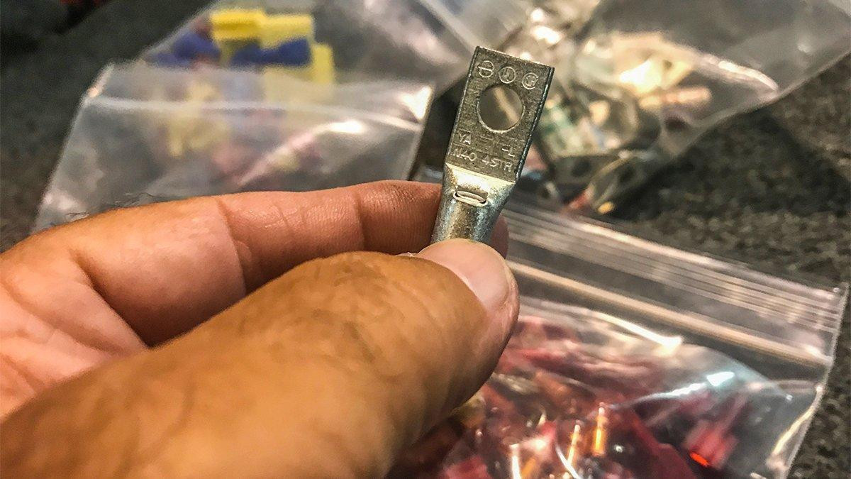
After many decades of troubleshooting and repairing boat wiring issues, I’ve become pretty darn good at figuring things out. Today’s boat wiring is one of the most difficult problems you’ll run across due to requirements of the numerous accessories.
For the last several weeks, I have been chasing a problem that has been causing me to lose sleep at night. Every time I think I have it fixed, it seems like another issue pops up and I’m back to square one. I finally conquered it by fixing a ground and using isolated power with a heavier guage wire.
This issue got me thinking that I’m probably not the only one that has experienced these headaches. So I wanted to make a short checklist that might help you if you run into a similar issue. If you’re just getting started working on your own boat wiring, these are some rules you should certainly follow.

Check for a wiring schematic
Unfortunately, not all boats have them. For as long as I can remember, however, Ranger has included one in most of their boats. Rather than purely guessing, having that roadmap can be huge when you’re tracking down problems.

Make detailed notes of any repairs
When adding accessories, it’s imperative to make clear notes in your phone or on a sheet of paper detailing how you rigged it. If a problem arises a few months after you did the work, you’re probably not going to remember exactly how everything is laid out.
I always use color-coded wire with red for positive and black for negative. This takes a lot the guesswork out of the problem solving.

High-grade connections and dielectric grease
Use high-grade connections and always use dielectric grease and shrink tubing on connections. You should never skip this step because it will save you a lot of trouble over time.
A good set of powerful crimpers are an excellent investment, too. Liquid tape is another inexpensive purchase that can protect against shorts. If you’re using electrical tape, make sure to cut it instead of pulling it when wrapping; it will stay on the wire much better.

Tighten terminals
Always tighten battery terminals snugly on the battery posts. A good rule of thumb is to put the smallest leads on the bottom. Use the box-end of the wrench when tightening as it is less likely to slip and bloody your knuckles.

Loose connections
A loose connection can cause a short or more resistance and which will keep your battery from performing optimally. Loose leads can use more power and significantly decrease your battery life.
Always hook up the positive lead first, too. I also replace all wing-style nuts with nylock. They hold much better and are less susceptible to loosening due to vibration.

Buy a good multi-meter
They are inexpensive and can solve a problem quickly. Battery power is DC, or direct current, so set up your meter for that. I also have a battery load tester, too. These can point out a bad cell quickly and save you a lot of time.
Here’s a good selection of multi-meters from Amazon.

Modern electronics eat power
Today’s electronics are big-time power hogs. A good group 27 or 31 battery is the best choice to power them and I strongly ecommend a deep cycle over a starting battery for this application because they hold a longer charge.

Use cable lubrication
When applicable, use lubrication when pulling wire through chases and never pull too hard; this can shred everything in the wire if you’re not careful. If it gets snug during the pull, back up and re-pull as nicks and scarring of the shielding can cause problems down the road including dead shorts.
Not only will your equipment not work, but bad wires can result in a fire.

Use zip ties to bundle wire
A limited amount of zip ties is the best choice as they can snag if wiring need to be worked on.
Never pull zip ties into a chase. Use ferrite rings or RF coils around electronics to dampen radio frequency interference. You can get ‘em cheap and they can be huge for removing trolling motor interference on electronics screens.

Use the proper wire gauge for the application
Load requirement and distance from the battery will help determine proper gauge wire and fuse requirements. For example, a trolling motor on a 20-foot boat should have 4 or 6 gauge wire for best battery utilization.
Every problem cannot be solved with this checklist, but it will give you a good starting place. Study schematics, never be afraid to attempt the job and if necessary, enlist expert help in the form of a reputable dealer or manufacturer and you can cut the down time significantly. Boat owners should never cut corners on wiring jobs.

With a BS in Radio/Television from Illinois State University, Terry Brown had the vision for Wired2fish. He currently serves as the President of Sales for Wired2fish. Prior to that he was director of sales at Bassfan. Brown is not only the best connector in the fishing industry, but he’s also the handiest man around a boat. He can fix just about anything on a boat from electronics to motors and everything in between, and the other team members always rely on him for answers on boat issues. He’s also an accomplished angler, radio host and writer. Another jack of all trades on this avid angling team.
Breaking News
Lew’s introduces custom lite shallow spool spinning reel, shimano, g.loomis and jackall release new tackle for spring 2024, angler snags world record paddlefish, 15.82-pound lunker bass caught from o.h. ivie, lowrance introduces new eagle fishfinder, connell wins bass pro tour redcrest 2024 championship, 4th largest bass in louisiana caught, pending lake record, seaguar adds three jdm lines to north american market, recent posts.

The 10 Best Fishing Apps

Yo-Zuri SuperFluoro 100% Fluorocarbon Leader Review

Best Fishing Deals from Amazon Spring Sale

When to Fish Weedless vs. Line-Through Swimbaits

Ark Essence Rod Review

Save Up To $500 on Live Sonar Transducers

Top Two Topwaters to Throw Early

39% Off Bass Pro Shops Power Series Deep Cycle AGM Marine Battery

Gamakatsu New Nano Alpha Hook Giveaway
843-297-8348 [email protected]
- E-Panel Builder
- Fully Custom
- Printed Contura II
- Etched Contura V
- Push Buttons
- Toggle Switches
- Circuit Protection
- Accessories (all)
- Marine Wire
- Battery Switches
- Mounting Panels
- Plugs & Chargers
- Terminal Blocks & Bus Bars
- Terminals & Lugs
- Deutsch Compatible Connectors
- Meters & Gauges
- Merch & Gift Cards
- 1. Panel Buyer’s Guide
- 2. Switch Panel Options
- 3. Panel Material
- 4. Switch Label Options
- 5. Printed vs. Etched Switch Covers
- 7. Wiring Diagrams
- 8. Boat Wiring Basics
- 9. Before and After
- 10. LuxMatte
- Panel Projects
WIRING DIAGRAMS & GENERAL GUIDES
We stock a wide variety of marine grade switches for your boat. From the classic toggle switch, to the popular Carling V-series rocker switch, to the new Bocatech push button switches. All our switches are sealed waterproof and dustproof. They are time tested, rugged and can all withstand the harsh marine environment.
With that being said, you may need some help wiring these switches. Below we have provided the information you will need to be able to get these switches wired up.
All switch diagrams from Rockers, Pushbuttons and Toggles.
Switch wiring diagrams based on the components you are controlling with the switch.
General wiring guides for backlighting, circuit breakers and more. Spec sheets on every switch that we carry online.
We carry a variety of switches. From Carling Rocker Switches to Bocatech Pushbuttons, we have all the diagrams you will need to get your switches up and running smoothly for your next trip out on the water.
Rocker Switches: Ensure you have the correct part number to match the switch you are trying to wire, we do have quite a few switches with similar pin-outs that require different wiring!
Push Buttons: Each manufacturer uses a specific color wire for something specific in these switches, whether you are using BlueWater, Bocatech or Carling, ensure you have the correct switch function and manufacture before using the diagram.
Toggle Switches: By far the easiest switches to the wire, ensure you have the right switch function before following the diagram all the way through.
If you are unsure of the switch diagram you need, reference the part number on your order or give our Customer Service Department a call.
Components are what you are operating with the switch. We have a wide variety of diagrams for components. When wiring up the components to the switches it is important to ensure that you are wiring the switch for the correct function of the component.
For Example, Trim Tabs are either Hydraulic or Electric. Electric trim tabs require Reverse Polarity wiring, while Hydraulic can be wired as normal. There are many different Trim Tabs out there, be sure to confirm with the Manufacture or check the spec sheet before wiring.
While we may not have specific diagrams for specific component manufacturers, you can still use the diagrams for the switches as a “general” guide.
General & Spec Sheets
We have many general diagrams to choose from that may be helpful in your wiring project. Our team of engineers has created a 13-page general boat wiring diagram. This diagram is for general use and non-specific scenarios. We also have general guides on wiring the backlit switches with circuit breakers or without, as well as general guides for the switches we carry.
While we can wire the Custom Dash Panels we create with the information given, it is best to confirm with a Marine Electrician if you have specific wiring questions. If you need someone in your area, check out our Local Installers page to find someone near you.
We know how important it is to make sure a product is going to work for you. We have listed all of the Spec Sheets for our switches and breakers in this section. We have also included hole cut sizes, how to cut our materials and more.
If you have specific questions, feel free to reach out to our Customer Service Department.
Boat Wiring Guide With Diagrams. How To Wire A Boat

When you buy a new Jon boat it is usually just a shell. But even after you have bought a new outboard motor to power your boat your job is not yet done. Not only do you need to wire your trolling motor to a battery but if you plan to navigate waters at night you may need to wire up navigational lights as well.
If you include fishfinders, search lights and other electronic goodies to your build then the wiring of your Jon boat can start to seem like a messy and daunting task.
Not to worry we are here to show you the basics of wiring your boat.
Staying safe should be your top priority when wiring a boat!
Plan and organize your boat wiring set-up before you begin – use boat wiring diagrams, 9 key points for wiring a boat switch panel, how to hide the boat wires after wiring a boat, how to insulate boat wires, video with easy practical steps for wiring a boat, additional resources that will help you build up knowledge on boat wiring, organizations to contact to learn more about boat wiring, a simple boat wiring diagram – basic 12 volt boat wiring diagram, 2 battery boat wiring diagram, full spec small boat wiring diagram, jon boat wiring diagram, in conclusion: how to wire boat lights & other boat electrical systems, when you need to know a bit about boat wiring.
If you are ready to do more with your Jon boat than resting on your oars, you will need to add power to your set-up.
Obviously the most common component on a boat, especially a Jon boat, which requires power is the trolling motor.

But, depending on the use of your boat there are a wide variety of other components and accessories that may need to be battery powered.
Battery operated boat components that need to be wired include:
- Navigation lights.
- Deck lighting and accessory lights.
- Bilge pump.
- Fish finders and Sonar.
- Control panels.
- On-board power banks and charging points.
Simultaneously connecting a range of items that a Jon boat needs to perform well for recreational boating, angling or hunting requires some basic electrical knowledge. It also requires a sound and logical approach to wiring your boat.
There are various approaches you can take for your Jon boat wiring set-up, and the approach you take will depend on your resources, the equipment and tools you have to hand and the functionality you want to achieve.
The most important thing to keep in mind before you start any electrical work on your boat is that electric is dangers even from a relatively small 12 V battery.
This is never more important than it is on a boat where you will be surrounded by water.
Boat wiring must be 100% protected from the elements as water is an electrical conductor – electric and water don’t mix well!
Untidy, piecemeal patch wiring jobs are dangerous and carry the risk of damage to your equipment, can start fires or even cause bodily harm or a fatality from electrocution.
55% of US Coastguard investigated boat fires are caused by faulty wiring. So, it is critical that you get the wiring of your boat right.
We have provided this information to give you an approach for wiring your boat effectively.
We strongly advise calling a professional marine electrician or surveyor if you feel out of your depth.
Be sure to also to use an electrician to review and ensure that the work you have undertaken yourself is electrically sound.
Key principles to wiring a boat
In this article we will outline key points and principles for basic wiring of your Jon boat with inclusion of a control panel to keep everything organized.
Wiring your Jon boat is as simple as following a boat wiring diagram. However you need to be aware of how to insulate and protect your electrical wires and connections before you begin.
We have included a video for wiring a Jon boat and several electrical boat wiring diagrams as well as links to some excellent additional resources.
These will assist you in accomplishing this task more effectively.
There is also a list of key pieces of kit that you will need to complete the job and also that will give a more resilient finish to your work.
11 items you will need to wire your Jon boat:
- A battery. Ideally you should have 2 batteries though for light electrical loads 1 battery will probably suffice.
- A main battery switch.
- A control panel.
- A reel of marine grade primary wire 8-14 AWG depending on the size of your boat.
- A negative bus bar.
- Waterproof in-line fuses.
- Spiral wrap or wire conduits.
- Wire tie mounts.
- Marine-grade butt connectors.
- Heat shrink wire wrap.
In addition you will need a regular selection of tools including a pencil or marker, wire cutters, pliers, drill, screwdrivers, a heat gun, hole saw and handheld power saw.
Protective eye-wear, gloves and a face-mask are also advisable.
Wiring a Jon boat can appear to be a daunting task when you first approach it but with careful planning and a good guide you can wire your boat in a single evening.
- You will need to sketch out or acquire a simple wiring plan for your boat which outlines the layout of the circuitry that needs to be connected. This will help in planning the equipment you need, wire lengths and key connections in your boat wiring. We have included several layout boat wiring diagrams (including a basic boat wiring diagram, a 2 battery boat wiring diagram, a full spec small boat wiring diagram and a Jon boat wiring diagram), at the end of this article.
- Ensure you identify and distinguish your positive (usually red) and negative (typically black) terminals on your battery, the control panel, and all the accessories that will become part of your Jon boat wiring set-up. Match like with like at all times.
- Power runs from your onboard battery to your control panel from which the power will be distributed to your connected equipment. The switches on the control panel essentially act as circuit-breakers that cut off power to the equipment that is not in use.
- You will need to correctly position all accessories and boat equipment, that is to be wired, in the correct place on your boat so you can run adequate lengths of your marine cabling to them. For example, if you are connecting a deck light make sure you position the light in the exact location on the deck where it will be used before you connect it to the battery or you may find that the cable you allocated for the connection is too short!
- Lay out and cut all the relevant lengths of cable on the boat according to your set-up boat wiring diagram. How many cables do you need? Cut that amount making sure you have enough length in each cable.
- When working with marine grade wire, have plenty on hand, and leave slack in your work for re-positioning, making corrections, upgrades and for making your final connections.
- It may be helpful to approach dealing with all positive wiring first and once that is completed focusing on the negative wiring connections afterwards.
- Your control panel will have connectors that allow you to splice wiring from your equipment into the control panel. You will need to attach complementary connectors to all wiring coming from your Jon boat equipment.
- Wire ends should be connected with appropriate marine-grade butt connectors. Install these heat shrink terminals using a heat gun to create a watertight seal. Heat shrink wire wrap can also be used to group wires together if needed.
- The connectors you use must be marine grade (corrosion resistant) and match the gauge of wire you are working with.
- A negative bus bar is used prior to connection of the negative wiring to the negative battery terminal to handle your boat’s negative load.
Masses of tangled and improperly connected boat wires are not only unsightly, they are dangerous!
Once you have established your wiring arrangement you can hold all your wiring together using a flexible wiring conduit of appropriate length.

You can also use cable ties and cable tie mounts.
In keeping with The American Boat and Yacht Council recommendation make sure electrical wires are secured at a minimum of at least every 18 inches.
3 ways to ensure that your boat electrics are properly protected
- Avoid overloading your writing, as this can cause short circuiting and fires.
- Fuses and circuit breakers should be sized below the amp rating of the equipment and accessories that are being protected.
- The American Boat and Yacht Council advises that they should be located within 7 inches of wire length from your power source.
- Do not use wire nuts for connections in your boat wiring, use ring or spade terminals with heat shrink tubing.
This wire is specifically manufactured to withstand the corrosive and abrasive environment experienced on boats.
Electrical tape, sleeves, padding and seals can also be used to insulate and protect your wiring, especially if it is run behind the ribs of the boat.
Videos and resources for successful & safe boat wiring
This is a relaxed run-through of the key steps you need to take to successfully wire your Jon boat.
- Boat circuits checklist
- Step-by-step guide for wiring any boat
- The boat builder’s handbook
- The American Boat and Yacht Council provides industry standards and education resources for wiring recreational vessels.
4 Boat wiring diagrams

If you are used to DIY projects on your Jon boat, wiring is going to be a task you will have to encounter at some point.
Despite the apparent simplicity of Jon boat wiring, safety is always paramount. Getting assistance from a professional or at least a boater who is experienced in marine wiring is prudent.
Once you have mastered the principles of safe wiring, the scope of your projects and the performance of your boat will increase massively.
Mick McGrath
Recent Content
DIY Boat Restoration: Tips and Tricks for a Budget-Friendly Makeover
Restoring an old boat can be a rewarding and cost-effective way to breathe new life into a beloved vessel. While it may seem like a daunting task, with the right tips and tricks, you can embark on...
518 Illustrated Boat Plans
518 boat plans for less than the price of your lunch! MyBoatPlans Reviews MyBoatPlans is a comprehensive collection of 518 boat plans, 40 videos and about 500 pages of boat building guides. I've...
IMAGES
VIDEO
COMMENTS
Even a small boat (3-5 loads) we'd recommend at least 12AWG wire for this. 10AWG for larger boats (5-10 loads) is normal. 8AWG is getting toward over-kill in most cases for boats under 30ft. Remember these are all generalities, there are many valid reasons to make exceptions.
Complete guide to wiring a boat electrical system from scratch. Starting from the 12V boat battery, we look at configuring a complete electrical system incl...
When you make your own wiring diagram use very large sheets of paper for clarity. Most boats will have positive and negative busses where area wires come together. Equipment coming off a switchboard or circuit panel should be straightforward to trace. On a small boat, sketching circuits in the boat outline helps you locate wires later.
A wiring diagram is a visual representation of the boat's electrical system and helps you identify the wires and their functions. A plan will help you organize the wiring, identify the locations of switches, panels, and other components, as well as ensure that the wiring is properly connected. Gather the Right Materials. It is important to be ...
Also known as 'chocolate block' or 'strip connectors'. These allow joints to be made and remade as required. Select the appropriate-sized terminal block for the wires to be connected. Using a wire stripper, remove just sufficient insulation to fit into the terminal. 'Chocolate block' connectors - no good for damp places.
Draw a square, label it with the name of the device (inverter, switch) and show the wires that are connected to it. For DC wiring, positive wires are red, negative wires are yellow (or black in some cases). Your boat wiring system should have a marine grade main battery disconnect switch which allows you to open the switch to turn everything ...
Although a fiberglass sailboat can seemingly have a half-life of 50 years or more, its electrical system most certainly does not. Up until the 1990s, few production builders used tinned wiring in their installations, and most owners had fairly basic requirements, allowing boatbuilders to get away with providing rudimentary electrical systems.
Boat electrical wiring from scratch: Part2. In this part we take wires from the electrical master switch to the boat main switch panel, and also from the 'n...
1. Wire A Boat. We've put together a this little newbie guide on How To Wire A Boat. It is by all means not-all inclusive, but should help some folks pickup some of the basics. View the complete guide here. 2. Wire A Bilge Pump. We recommend an ON-OFF switch for small boat bilge pumps with a a separate fused feed to the float switch direct ...
Our review of Boat Electrics 101, a new online course, co-developed by marine electrics expert, Nigel Calder. When we bought our 1970s-era sailboat, the boat wiring was a disaster. We soon discovered a rainbow spaghetti mess of unlabeled electrical wires behind our DC electrical panel. Legacy marine electrical systems from a previous ...
A simple wiring diagram showing the battery, engine block ground, and ground bus-bar Why is a Ground Important on a Boat? If an electronic device develops a short-circuit from the power-supply side to the equipment's metal case, the case would then be "hot" and would be a potentially dangerous source of electrical shock or ignition.
Wiring Diagrams 19-21 Glossary of Terms 22-23 FAQs (Frequently Asked Questions) 24. 4 understandinG your Boat's electrical systeM Getting to the Heart of the Matter Your boat's AC electric system is a lot like your body's circulatory system. Your heart pumps blood throughout your body via a network of arteries. These arter-
Here is a web site where you can obtain wiring diagrams for most outboard motors. Most new outboards come with a wiring harness and a manual that has wiring diagrams. See Master Tech Marine Outboard Wiring Diagrams. Note 2: If you are re-wiring a boat with an electrical system installed: Don't rip out that old system yet! Use the old system to ...
Boat lectical base kits: https://tbnation.net/products/weekend-warrior-electrical-kitTrolling motor wiring kits: https://tbnation.net/products/trolling-motor...
The Boat Electrics 101 course is a fantastic resource for beginners like myself who know little about electricity and even less about boats electrical systems. Clearly expressed and illustrated, the course is full of practical information presented in a way that makes boat electrical systems understandable.
JoeWhite. Catalina 1999 C36 MKII #1787 Coyote Point Marina, CA. There is a "language" to drawing wiring diagram. To draw such that the reader understands the diagram requires electrical engineering training. There are templates you can buy to draw devices such as relays, terminal blocks, etc.
Use the proper wire gauge for the application. Load requirement and distance from the battery will help determine proper gauge wire and fuse requirements. For example, a trolling motor on a 20-foot boat should have 4 or 6 gauge wire for best battery utilization.
I rewired my Tayana 37 in much the same way. I found the wiring to be much the same; original non-tinned wire with significant corrosion. The only solution was to rewire this 45 year old boat from the keel up. I noted no bilge pump in your wiring diagram. I have 3 on my boat that are directly switched, wired, and fused to my house batteries.
1. Plan Your Wiring System. Before you start wiring your small boat, it's important to have a plan in place. Identify the electrical components you will need, such as lights, pumps, and navigation equipment, and determine their locations on the boat. This will help you determine the length and type of wiring required.
Electric trim tabs require Reverse Polarity wiring, while Hydraulic can be wired as normal. There are many different Trim Tabs out there, be sure to confirm with the Manufacture or check the spec sheet before wiring. ... Our team of engineers has created a 13-page general boat wiring diagram. This diagram is for general use and non-specific ...
This will help in planning the equipment you need, wire lengths and key connections in your boat wiring. We have included several layout boat wiring diagrams (including a basic boat wiring diagram, a 2 battery boat wiring diagram, a full spec small boat wiring diagram and a Jon boat wiring diagram), at the end of this article.