My Cruiser Life Magazine

Basics of Sailboat Hull Design – EXPLAINED For Owners
There are a lot of different sailboats in the world. In fact, they’ve been making sailboats for thousands of years. And over that time, mankind and naval architects (okay, mostly the naval architects!) have learned a thing or two.
If you’re wondering what makes one sailboat different from another, consider this article a primer. It certainly doesn’t contain everything you’d need to know to build a sailboat, but it gives the novice boater some ideas of what goes on behind the curtain. It will also provide some tips to help you compare different boats on the water, and hopefully, it will guide you towards the sort of boat you could call home one day.
Table of Contents
Displacement hulls, semi displacement hulls, planing hulls, history of sailboat hull design, greater waterline length, distinctive hull shape and fin keel designs, ratios in hull design, the hull truth and nothing but the truth, sail boat hull design faqs.

Basics of Hull Design
When you think about a sailboat hull and how it is built, you might start thinking about the shape of a keel. This has certainly spurred a lot of different designs over the years, but the hull of a sailboat today is designed almost independently of the keel.
In fact, if you look at a particular make and model of sailboat, you’ll notice that the makers often offer it with a variety of keel options. For example, this new Jeanneau Sun Odyssey comes with either a full fin bulb keel, shallow draft bulb fin, or very shallow draft swing keel. Where older long keel designs had the keel included in the hull mold, today’s bolt-on fin keel designs allow the manufacturers more leeway in customizing a yacht to your specifications.
What you’re left with is a hull, and boat hulls take three basic forms.
- Displacement hull
- Semi-displacement hulls
- Planing hulls
Most times, the hull of a sailboat will be a displacement hull. To float, a boat must displace a volume of water equal in weight to that of the yacht. This is Archimedes Principle , and it’s how displacement hulled boats get their name.
The displacement hull sailboat has dominated the Maritimes for thousands of years. It has only been in the last century that other designs have caught on, thanks to advances in engine technologies. In short, sailboats and sail-powered ships are nearly always displacement cruisers because they lack the power to do anything else.
A displacement hull rides low in the water and continuously displaces its weight in water. That means that all of that water must be pushed out of the vessel’s way, and this creates some operating limitations. As it pushes the water, water is built up ahead of the boat in a bow wave. This wave creates a trough along the side of the boat, and the wave goes up again at the stern. The distance between the two waves is a limiting factor because the wave trough between them creates a suction.
This suction pulls the boat down and creates drag as the vessel moves through the water. So in effect, no matter how much power is applied to a displacement hulled vessel, it cannot go faster than a certain speed. That speed is referred to as the hull speed, and it’s a factor of a boat’s length and width.
For an average 38 foot sailboat, the hull speed is around 8.3 knots. This is why shipping companies competed to have the fastest ship for many years by building larger and larger ships.
While they might sound old-school and boring, displacement hulls are very efficient because they require very little power—and therefore very little fuel—to get them up to hull speed. This is one reason enormous container ships operate so efficiently.

Of course, living in the 21st century, you undoubtedly have seen boats go faster than their hull speed. Going faster is simply a matter of defeating the bow wave in one way or another.
One way is to build the boat so that it can step up onto and ride the bow wave like a surfer. This is basically what a semi-displacement hull does. With enough power, this type of boat can surf its bow wave, break the suction it creates and beat its displacement hull speed.
With even more power, a boat can leave its bow wave in the dust and zoom past it. This requires the boat’s bottom to channel water away and sit on the surface. Once it is out of the water, any speed is achievable with enough power.
But it takes enormous amounts of power to get a boat on plane, so planing hulls are hardly efficient. But they are fast. Speedboats are planing hulls, so if you require speed, go ahead and research the cost of a speedboat .
The most stable and forgiving planing hull designs have a deep v hull. A very shallow draft, flat bottomed boat can plane too, but it provides an unforgiving and rough ride in any sort of chop.

If you compare the shapes of the sailboats of today with the cruising boat designs of the 1960s and 70s, you’ll notice that quite a lot has changed in the last 50-plus years. Of course, the old designs are still popular among sailors, but it’s not easy to find a boat like that being built today.
Today’s boats are sleeker. They have wide transoms and flat bottoms. They’re more likely to support fin keels and spade rudders. Rigs have also changed, with the fractional sloop being the preferred setup for most modern production boats.
Why have boats changed so much? And why did boats look so different back then?
One reason was the racing standards of the day. Boats in the 1960s were built to the IOR (International Offshore Rule). Since many owners raced their boats, the IOR handicaps standardized things to make fair play between different makes and models on the racecourse.
The IOR rule book was dense and complicated. But as manufacturers started building yachts, or as they looked at the competition and tried to do better, they all took a basic form. The IOR rule wasn’t the only one around . There were also the Universal Rule, International Rule, Yacht Racing Association Rul, Bermuda Rule, and a slew of others.
Part of this similarity was the rule, and part of it was simply the collective knowledge and tradition of yacht building. But at that time, there was much less distance between the yachts you could buy from the manufacturers and those setting off on long-distance races.
Today, those wishing to compete in serious racing a building boat’s purpose-built for the task. As a result, one-design racing is now more popular. And similarly, pleasure boats designed for leisurely coastal and offshore hops are likewise built for the task at hand. No longer are the lines blurred between the two, and no longer are one set of sailors “making do” with the requirements set by the other set.
Modern Features of Sailboat Hull Design
So, what exactly sets today’s cruising and liveaboard boats apart from those built-in decades past?
Today’s designs usually feature plumb bows and the maximum beam carried to the aft end. The broad transom allows for a walk-through swim platform and sometimes even storage for the dinghy in a “garage.”
The other significant advantage of this layout is that it maximizes waterline length, which makes a faster boat. Unfortunately, while the boats of yesteryear might have had lovely graceful overhangs, their waterline lengths are generally no match for newer boats.
The wide beam carried aft also provides an enormous amount of living space. The surface area of modern cockpits is nothing short of astounding when it comes to living and entertaining.
If you look at the hull lines or can catch a glimpse of these boats out of the water, you’ll notice their underwater profiles are radically different too. It’s hard to find a full keel design boat today. Instead, fin keels dominate, along with high aspect ratio spade rudders.
The flat bottom boats of today mean a more stable boat that rides flatter. These boats can really move without heeling over like past designs. Additionally, their designs make it possible in some cases for these boats to surf their bow waves, meaning that with enough power, they can easily achieve and sometimes exceed—at least for short bursts—their hull speeds. Many of these features have been found on race boats for decades.
There are downsides to these designs, of course. The flat bottom boats often tend to pound when sailing upwind , but most sailors like the extra speed when heading downwind.

How Do You Make a Stable Hull
Ultimately, the job of a sailboat hull is to keep the boat afloat and create stability. These are the fundamentals of a seaworthy vessel.
There are two types of stability that a design addresses . The first is the initial stability, which is how resistant to heeling the design is. For example, compare a classic, narrow-beamed monohull and a wide catamaran for a moment. The monohull has very little initial stability because it heels over in even light winds. That doesn’t mean it tips over, but it is relatively easy to make heel.
A catamaran, on the other hand, has very high initial stability. It resists the heel and remains level. Designers call this type of stability form stability.
There is also secondary stability, or ultimate stability. This is how resistant the boat is to a total capsize. Monohull sailboats have an immense amount of ballast low in their keels, which means they have very high ultimate stability. A narrow monohull has low form stability but very high ultimate stability. A sailor would likely describe this boat as “tender,” but they would never doubt its ability to right itself after a knock-down or capsize.
On the other hand, the catamaran has extremely high form stability, but once the boat heels, it has little ultimate stability. In other words, beyond a certain point, there is nothing to prevent it from capsizing.
Both catamarans and modern monohulls’ hull shapes use their beams to reduce the amount of ballast and weight . A lighter boat can sail fast, but to make it more stable, naval architects increase the beam to increase the form stability.
If you’d like to know more about how stable a hull is, you’ll want to learn about the Gz Curve , which is the mathematical calculation you can make based on a hull’s form and ultimate stabilities.
How does a lowly sailor make heads or tails out of this? You don’t have to be a naval architect when comparing different designs to understand the basics. Two ratios can help you predict how stable a design will be .
The first is the displacement to length ratio . The formula to calculate it is D / (0.01L)^3 , where D is displacement in tons and L is waterline length in feet. But most sailboat specifications, like those found on sailboatdata.com , list the D/L Ratio.
This ratio helps understand how heavy a boat is for its length. Heavier boats must move more water to make way, so a heavy boat is more likely to be slower. But, for the ocean-going cruiser, a heavy boat means a stable boat that requires much force to jostle or toss about. A light displacement boat might pound in a seaway, and a heavy one is likely to provide a softer ride.
The second ratio of interest is the sail area to displacement ratio. To calculate, take SA / (D)^0.67 , where SA is the sail area in square feet and D is displacement in cubic feet. Again, many online sites provide the ratio calculated for specific makes and models.
This ratio tells you how much power a boat has. A lower ratio means that the boat doesn’t have much power to move its weight, while a bigger number means it has more “get up and go.” Of course, if you really want to sail fast, you’d want the boat to have a low displacement/length and a high sail area/displacement.
Multihull Sailboat Hulls
Multihull sailboats are more popular than ever before. While many people quote catamaran speed as their primary interest, the fact is that multihulls have a lot to offer cruising and traveling boaters. These vessels are not limited to coastal cruising, as was once believed. Most sizable cats and trimarans are ocean certified.
Both catamarans and trimaran hull designs allow for fast sailing. Their wide beam allows them to sail flat while having extreme form stability.

Catamarans have two hulls connected by a large bridge deck. The best part for cruisers is that their big surface area is full of living space. The bridge deck usually features large, open cockpits with connecting salons. Wrap around windows let in tons of light and fresh air.
Trimarans are basically monohulls with an outrigger hull on each side. Their designs are generally less spacious than catamarans, but they sail even faster. In addition, the outer hulls eliminate the need for heavy ballast, significantly reducing the wetted area of the hulls.
Boaters and cruising sailors don’t need to be experts in yacht design, but having a rough understanding of the basics can help you pick the right boat. Boat design is a series of compromises, and knowing the ones that designers and builders take will help you understand what the boat is for and how it should be used.
What is the most efficient boat hull design?
The most efficient hull design is the displacement hull. This type of boat sits low in the water and pushes the water out of its way. It is limited to its designed hull speed, a factor of its length. But cruising at hull speed or less requires very little energy and can be done very efficiently.
By way of example, most sailboats have very small engines. A typical 40-foot sailboat has a 50 horsepower motor that burns around one gallon of diesel every hour. In contrast, a 40-foot planing speedboat may have 1,000 horsepower (or more). Its multiple motors would likely be consuming more than 100 gallons per hour (or more). Using these rough numbers, the sailboat achieves about 8 miles per gallon, while the speedboat gets around 2 mpg.
What are sail boat hulls made of?
Nearly all modern sailboats are made of fiberglass.
Traditionally, boats were made of wood, and many traditional vessels still are today. There are also metal boats made of steel or aluminum, but these designs are less common. Metal boats are more common in expedition yachts or those used in high-latitude sailing.

Matt has been boating around Florida for over 25 years in everything from small powerboats to large cruising catamarans. He currently lives aboard a 38-foot Cabo Rico sailboat with his wife Lucy and adventure dog Chelsea. Together, they cruise between winters in The Bahamas and summers in the Chesapeake Bay.
- News & Views
- Boats & Gear
- Lunacy Report
- Techniques & Tactics
MODERN SAILBOAT DESIGN: Quantifying Stability

We have previously discussed both form stability and ballast stability as concepts, and these certainly are useful when thinking about sailboat design in the abstract. They are less useful, however, when you are trying to evaluate individual boats that you might be interested in actually buying. Certainly you can look at any given boat, ponder its shape, beam, draft, and ballast, and make an intuitive guess as to how stable it is, but what’s really wanted is a simple reductive factor–similar to the displacement/length ratio , sail-area/displacement ratio , or Brewer comfort ratio –that allows you to effectively compare one boat to another.
Unfortunately, it is impossible to thoroughly analyze the stability of any particular sailboat using commonly published specifications. Indeed, stability is so complex and is influenced by so many factors that even professional yacht designers find it hard to quantify. Until the advent of computers, the calculations involved were so overwhelming that certain aspects of stability were only estimated rather than precisely determined. Even today, with computers doing all the heavy number crunching, stability calculations remain the most tedious part of a naval architect’s job.
There are, however, some tools available that you can use to make a sophisticated appraisal of a boat’s stability characteristics. If you dig and scratch a bit–on the Internet, or by pestering a builder or designer–you should be able to unearth one or more of them.
Stability Curves and Ratios
The most common tool used to assess a boat’s form and ballast stability is a stability curve. This is a graphic representation of a boat’s self-righting ability as it is rotated from right side up to upside down. Stability curves are sometimes published or otherwise made available by designers and builders, but to interpret them correctly, you first need to understand the physics of a heeling sailboat.
When perfectly upright, a boat’s center of gravity (CG)–which is a function of its total weight distribution (i.e., its ballast stability)–and its center of buoyancy (CB)–which is a function of its hull shape (i.e., its form stability)–are vertically aligned on the boat’s centerline. CG presses downward on the boat’s hull while CB presses upward with equal force. The two are in perfect equilibrium, and the boat is motionless. If some force heels the boat, however, CB shifts outboard of CG and the equilibrium is disturbed. The horizontal distance created between CG and CB as the boat heels is called the righting arm (GZ). This is a lever arm, with CG pushing down on one end and CB pushing up on the other, and their combined force, known as the righting moment (RM), works to rotate the hull back to an upright position. The point around which the hull rotates is known as the metacenter (M) and is always directly above CB.
The longer the righting arm (i.e., the larger the value for GZ), the greater the righting moment and the harder the hull tries to swing upright again. Up to a point, as a hull heels more, its righting arm just gets longer. The righting moment, consequently, gets larger and larger. This is initial stability. A wider hull has greater initial stability simply because its greater beam allows CB to move farther away from CG as it heels. Shifting ballast to windward also moves CG farther away from CB, and this too lengthens the righting arm and increases initial stability. The angle of maximum stability (AMS) is the angle at which the righting arm for any given hull is as long as it can be. This is where a hull is trying its hardest to turn upright again and is most resistant to further heeling.
Once a hull is pushed past its AMS, its righting arm gets progressively shorter and its ability to resist further heeling decreases. Now we are moving into the realm of ultimate, or reserve, stability. Eventually, if the hull is pushed over far enough, the righting arm disappears and CG and CB are again vertically aligned. Now, however, the metacenter and CG are in the same place, and the hull is metastable, meanings it is in a state of anti-equilibrium. Its fate hangs in the balance, and the least disturbance will cause it to turn one way or the other. This point of no return is the angle of vanishing stability (AVS). If the hull fails to right itself at this point, it must capsize. Any greater angle of heel will cause CG and CB to separate again, except now the horizontal distance between them will be a capsizing arm, not a righting arm. Gravity and buoyancy will be working together to invert the hull.
Stability at work. The righting arm (GZ) gets longer as the center of gravity (CG) and the center of buoyancy (CB) get farther apart, and the boat works harder to right itself. Past the angle of vanishing stability, however, the righting arm is negative and CG and CB are working to capsize the boat
A stability curve is simply a plot of GZ–including both the positive righting arm and the negative capsizing arm–as it relates to angle of heel from 0 to 180 degrees. Alternatively, RM (that is, both the positive righting moment and the negative capsizing moment) can be the basis of the plot, as it derives directly from GZ. (To find RM in foot-pounds, simply multiply GZ in feet by the boat’s displacement in pounds.) In either case, an S-curve plot is typical, with one hump in positive territory and another hopefully smaller hump (assuming the boat in question is a monohull) in negative territory.
The AMS is the highest point on the positive side of the curve; the AVS is the point at which the curve moves from positive to negative territory. The area under the positive hump represents all the energy that must be expended by wind and waves to capsize the boat; the area under the negative hump is the energy (usually only waves come into play here) required to right the boat again. To put it another way: the larger the positive hump, the more likely a boat is to remain right side up; the smaller the negative hump, the less likely it is to remain upside down.
Righting arm (GZ) stability curve for a typical 35-foot cruising boat. The angle of maximum stability (AMS) in this case is 55 degrees with a maximum GZ of 2.6 feet; the angle of vanishing stability (AVS) is 120 degrees; the minimum GZ is -0.8 feet
The relationship between the sizes of the two humps is known as the stability ratio. If you have a stability curve to work from, there are some simple calculations developed by designer Dave Gerr that allow you to estimate the area under each portion of the curve. To calculate the positive energy area (PEA), simply multiply the AVS by the maximum righting arm and then by 0.63: PEA = AVS x max. GZ x 0.63. To calculate the negative energy area (NEA), first subtract the AVS from 180, then multiply the result by the maximum capsizing arm (i.e., the minimum GZ) and then by 0.66: NEA = (180 – AVS) x min. GZ x 0.66. To find the stability ratio divide the positive area by the negative area.
Working from the curve shown in the graph above for a typical 35-foot cruising boat, we get the following values to plug into our equations: AVS = 120 degrees; max. GZ = 2.6 feet; min. GZ = -0.8 feet. The boat’s PEA therefore is 196.56 degree-feet: 120 x 2.6 x 0.63 = 196.56. Its NE is 31.68 degree-feet: (180 – 120) x -0.8 x 0.66 = 31.68. Its stability ratio is thus 6.2: 196.56 ÷ 31.68 = 6.2. As a general rule, a stability ratio of at least 3 is considered adequate for coastal cruising boats; 4 or greater is considered adequate for a bluewater boat. The boat in our example has a very healthy ratio, though some boats exhibit ratios as high as 10 or greater.
You can run these same equations regardless of whether you are working from a curve keyed to the righting arm or the righting moment. The curve in our example is a GZ curve, but if it were an RM curve, we only have to substitute the values for maximum and minimum RM for maximum and minimum GZ. Otherwise the equations run exactly the same way. The results for positive and negative area, assuming RM is expressed in foot-pounds, will be in degree-foot-pounds rather than degree-feet, but the final ratio will be unaffected.
GZ and RM curves are not, however, interchangeable in all respects. When evaluating just one boat it makes little difference which you use, but when comparing different boats you should always use an RM curve. Because righting moment is a function of both a boat’s displacement and the length of its righting arm, RM is the appropriate standard for comparing boats of different displacements. It is possible for different boats to have the same righting arm at any angle of heel, but they are unlikely to have the same stability characteristics. It always takes more energy to capsize a larger, heavier boat, which is why bigger boats are inherently more stable than smaller ones.
Righting moment (RM) stability curves for a 19,200-pound boat and a 28,900-pound boat with identical GZ values. Because heavier boats are inherently more stable, RM is the standard to use when comparing different boats (Data courtesy of Dave Gerr)
Another thing to bear in mind when comparing boats is that not all stability curves are created equal. There are various methods for constructing the curves, each based on different assumptions. The two most commonly used methodologies are based on standards promulgated by the International Measurement System (IMS), a once popular rating rule used in international yacht racing, and by the International Organization for Standardization (ISO). Many yacht designers have developed their own methods. When comparing different boats, you must therefore be sure their curves were constructed according to the same method.
Perfect Curves and Vanishing Angles
To get a better idea of how form and ballast relate to each another, it is useful to compare curves for hypothetical ideal vessels that depend exclusively on one type of stability or the other. A vessel with perfect form stability, for example, would be shaped very much like a wide flat board, and its stability curve would be perfectly symmetrical. Its AVS would be 90 degrees, and it would be just as stable upside down as right side up. A vessel with perfect ballast stability, on the other hand, would be much like a ballasted buoy–that is, a round, nearly weightless flotation ball with a long stick on one side to which a heavy weight is attached, like a pick-up buoy for a mooring or a man-overboard pole. The curve for this vessel would have no AVS at all; there would be just one perfectly symmetric hump with an angle of maximum stability of 90 degrees. The vessel will not become metastable until it reaches the ultimate heeling angle of 180 degrees, and no matter which way it turns at this point, it must right itself.
Ideal righting arm (GZ) stability curves: vessel A, a flat board, is as stable upside down as it is right side up; vessel B, a ballasted buoy, must right itself if turned upside down (Data courtesy of Danny Greene)
Beyond the fact that one curve has no AVS at all and the other has a very poor one, the most obvious difference between the two is that the board (vessel A) reaches its point of no return at precisely the point that the buoy (vessel B) achieves maximum stability. A subtler but critical difference is seen in the shape of the two curves between 0 and 30 degrees of heel, which is the range within which sailboats routinely operate. Vessel A achieves its maximum stability precisely at 30 degrees, and the climb of its curve to that point is extremely steep, indicating high initial stability. Vessel B, on the other hand, exhibits poor initial stability, as the trajectory of its curve to 30 degrees is gentle. Indeed, heeling A to just 30 degrees requires as much energy as is needed to knock B down flat to 90 degrees.
Righting arm (GZ) stability curves for a typical catamaran and a typical narrow, deep-draft, heavily ballasted monohull. Note similarities to the ideal curves in the last figure
To translate this into real-world terms, we need only compare the curves for two real-life vessels at opposite extremes of the stability spectrum. The curve for a typical catamaran, for example, looks similar to that of our board since its two humps are symmetrical. If anything, however, it is even more exaggerated. The initial portion of the curve is extremely steep, and maximum stability is achieved at just 10 degrees of heel. The AVS is actually less than 90 degrees, meaning that the cat, due to the weight of its superstructure and rig, will reach its point of no return even before it is knocked down to a horizontal position. The curve for a narrow, deep-draft, heavily ballasted monohull, by comparison, is similar to that of the ballasted buoy. The only significant difference is that the monohull has an AVS, though it is quite high (about 150 degrees), and its range of instability (that is, the angles at which it is trying to capsize rather than right itself) is very small, especially when compared to that of the catamaran.
The catamaran, due to its light displacement and great initial stability, will likely perform well in moderate conditions and will heel very little, but it has essentially no reserve stability to rely on when conditions get extreme. The monohull because of its heavy displacement (much of it ballast) and great reserve stability, will perform less well in moderate conditions but will be nearly impossible to overturn in severe weather.
What Is An Adequate AVS?
In the real world you will rarely come across stability curves for catamarans. If you do find one, you should probably be most interested in the AMS and the steepness of the curve leading up to it. Monohull sailors, on the other hand, should be most interested in the AVS, and as a general rule the bigger this is the better.
Coastal cruisers sailing in protected waters should theoretically be perfectly safe in a boat with an AVS of just 90 degrees. Assuming you never encounter huge waves, the worst that could happen is you will be knocked flat by the wind, and so as long as you can recover from a 90-degree knockdown, you should be fine. It’s nice to have a safety margin, however, so most experts advise that average-size coastal cruising boats should have an AVS of at least 110 degrees. Some believe the minimum should 115 degrees.
For offshore sailing you want a larger margin of safety. Recovering from a knockdown in high winds is one thing, but in a survival storm, with both high winds and large breaking waves, there will be large amounts of extra energy available to help roll your boat past horizontal. There is near-universal consensus that bluewater boats less than 75 feet long should have an AVS of at least 120 degrees. Because larger boats are inherently more stable, the standard for boats longer than 75 feet is 110 degrees.
The reason 120 degrees is considered the minimum AVS standard for most bluewater boats is quite simple. Naval architects figure that any sea state rough enough to roll a boat past 120 degrees and totally invert it will also be rough enough to right it again in no more than 2 minutes. This, it is assumed, is the longest time most people can hold their breaths while waiting for their boats to right themselves. If you don’t ever want to hold your breath that long, you want to sail offshore in a boat with a higher AVS.
Estimated times of inversion for different AVS values (Data courtesy of Dave Gerr)
As this graph illustrates, an AVS of 150 degrees is pretty much the Holy Grail. A boat with this much reserve stability can expect to meet a wave large enough to turn it right side up again almost the instant it’s turned over.
Other Factors To Consider
Stability curves may look dynamic and sophisticated, but in fact they are based on relatively simple formulas that can’t account for everything that might make a particular boat more or less stable in the real world. For one thing, as with regular performance ratios, the displacement values used in calculating stability curves are normally light-ship figures and do not include the weight that is inevitably added when a boat is equipped and loaded for cruising. Even worse, much of this extra weight–in the form of roller-furling units, mast-mounted radomes, and other heavy gear–will be well above the waterline and thus will erode a boat’s inherent stability. The effect can be quite large. For example, installing an in-mast furling system may reduce your boat’s AVS by as much as 20 degrees. In most cases, you should assume that a loaded cruising boat will have an AVS at least 10 degrees lower than that indicated on a stability curve calculated with a light-ship displacement number.
Another important factor to consider is downflooding. Stability curves normally assume that a boat will take on no water when knocked down past 90 degrees, but this is unlikely in the real world. The companionway hatch will probably be at least partway open, and if the knockdown is unexpected, other hatches may be open as well. Water entering a boat that is heeled to an extreme angle will further destabilize the boat by shifting weight to its low side. If the water sloshes about, as is likely, this free-surface effect will make it even harder for the boat to come upright again.
This may seem irrelevant if you are a coastal cruiser, but if you are a bluewater cruiser you should be aware of the location of your companionway. A centerline companionway will rarely start downflooding until a boat is heeled to 110 degrees or more. An offset companionway, however, if it is on the low side of the boat as it heels, may yield downflood angles of 100 degrees or lower. A super AVS of 150 degrees won’t do much good if your boat starts flooding well before that. To my knowledge, no commonly published stability curve accounts for this factor.
Another issue is the cockpit. An open-transom cockpit, or a relatively small one with large effective drains, will drain quickly if flooded in a knockdown. A large cockpit that drains poorly, however, may retain water for several minutes, and this, too, can destabilize a boat that is struggling to right itself.
This boat has features that can both degrade and improve its stability. The severely offset companionway makes downflooding a big risk during a port tack knockdown or capsize, but the high rounded cabintop and small cockpit footwell will help the boat to right itself
Fortunately, not all unaccounted for stability factors are negative. IMS-based stability curves, for example, assume that all boats have flush decks and ignore the potentially positive effect of a cabin house. This is important, as a raised house, particularly one with a rounded top, provides a lot of extra buoyancy as it is submerged and can significantly increase a boat’s stability at severe heel angles. Lifeboats and other self-righting vessels have high round cabintops for precisely this reason.
ISO-based stability curves do account for a raised cabin house, but not all designers believe this is a good thing. A cabin house only increases reserve stability if it is impervious to flooding when submerged. If it has open hatches or has large windows and apertures that may break under pressure, it will only help a boat capsize and sink that much faster. The ISO formulas fail to take this into account and instead may award high stability ratings to motorsailers and deck-saloon boats with large houses and windows that may be vulnerable in extreme conditions.
Simplified Measures of Stability
In addition to developing stability curves, which obviously are fairly complex, designers and rating and regulatory authorities have also worked to quantify a boat’s stability with a single number. The simplest of these, the capsize screening value (CSV), was developed in the aftermath of the 1979 Fastnet Race. Over a third of the more than 300 boats entered in that race, most of them beamy, lightweight IOR designs, were capsized (rolled to 180 degrees) by large breaking waves, and this prompted a great deal of research on yacht stability. The capsize screening value, which relies only on published specifications and was intended to be accessible to laypeople, indicates whether a given boat might be too wide and light to readily right itself after being overturned in extreme conditions.
To figure out a boat’s CSV divide the cube root of its displacement in cubic feet into its maximum beam in feet: CSV = beam ÷ ³√DCF. You’ll recall that a boat’s weight and the volume of water it displaces are directly related, and that displacement in cubic feet is simply displacement in pounds divided by 64 (which is the weight in pounds of a cubic foot of salt water). To run an example of the equation, let’s assume we have a hypothetical 35-foot boat that displaces 12,000 pounds and has 11 feet of beam. To find its CSV, first calculate DCF–12,000 ÷ 64 = 187.5–then find the cube root of that result: ³√187.5 = 5.72; note that if your calculator cannot do cube roots, you can instead take 187.5 to the 1/3 power and get the same result. Divide that result into 11, and you get a CSV of 1.92: 11 ÷ 5.72 = 1.92.
Interpreting the number is also simple. Any result of 2 or less indicates a boat that is sufficiently self-righting to go offshore. The further below 2 you go, the more self-righting the boat is; extremely stable boats have values on the order of 1.7. Results above 2 indicate a boat may be prone to remain inverted when capsized and that a more detailed analysis is needed to determine its suitability for offshore sailing.
As handy as it is, the CSV has limited utility. It accounts for only two factors–displacement and beam–and fails to consider how weight is distributed aboard a boat. For example, if we load our hypothetical 12,000-pound boat with an extra 2,250 pounds for light coastal cruising, its CSV declines to 1.8. Load it with an extra 3,750 pounds for heavy coastal or moderate bluewater use, and the CSV declines still further, to 1.71. This suggests that the boat is becoming more stable, when in fact it may become less stable if much of the extra weight is distributed high in the boat.
Note too that a boat with unusually high ballast–including, most obviously, a boat with ballast in its bilges rather than its keel–will also earn a deceptively low screening value. Two empty boats of identical displacement and beam will have identical screening values even though the boat with deeper ballast will necessarily be more resistant to capsize.
Another single-value stability rating still frequently encountered is the IMS stability index number. This was developed under the IMS rating system to compare stability characteristics of race boats of various sizes. The formula essentially restates a boat’s AVS so as to account for its overall size, awarding higher values to longer boats, which are inherently more stable. IMS index numbers normally range from a little below 100 to over 140. For what are termed Category 0 races, which are transoceanic events, 120 is usually the required minimum. In Category 1 events, which are long-distances races sailed “well offshore,” 115 is the common minimum standard, and for Category 2 events, races of extended duration not far from shore, 110 is normally the minimum standard. Conservative designers and pundits often posit 120 as the acceptable minimum for an offshore cruising boat.
Since many popular cruising boats were never measured or rated under the IMS rule, you shouldn’t be surprised if you cannot find an IMS-based stability curve or stability index number for a cruising boat you are interested in. You may find one if the boat in question is a cruiser-racer, as IMS was once a prevalent rating system. Bear in mind, though, that the IMS index number does not take into account cabin structures (or cockpits, for that matter), and assumes a flush deck from gunwale to gunwale. Neither does it account for downflooding.
Another single-value stability rating that casts itself as an “index” is promulgated by the ISO. This is known as STIX, which is simply a trendy acronym for stability index. Because STIX values must be calculated for any new boat sold inside the European Union (EU), and because STIX is, in fact, the only government-imposed stability standard in use anywhere in the world, it is likely to become the predominant standard in years to come.
A STIX number is the result of many complex calculations accounting for a boat’s length, displacement, beam, ability to shed water after a knockdown, angle of vanishing stability, downflooding, cabin superstructure, and freeboard in breaking seas, among others. STIX values range from the low single digits to about 50. A minimum of 38 is required by the European Union for Category A boats, which are certified for use on extended passages more than 500 miles offshore where waves with a maximum height of 46 feet may be encountered. A value of at least 23 is required for Category B boats, which are certified for coastal use within 500 miles of shore where maximum wave heights of 26 feet may be encountered, and the minimum values for categories C and D (inshore and sheltered waters, respectively) are 14 and 5. These standards do not restrict an owner’s use of his boat, but merely dictate how boats may be marketed to the public.
The STIX standard has many critics, including many yacht designers who do not enjoy having to make the many calculations involved, but the STIX number is the most comprehensive single measure of stability now available. As such, it can hardly be ignored. Many critics assert that the standards are too low and that a number of 40 or greater is more appropriate for Category A boats and 30 or more is best for Category B boats. Others believe that in trying to account for and quantify so many factors in a single value, the STIX number oversimplifies a complex subject. To properly evaluate stability, they suggest, it is necessary to evaluate the various factors independently and make an informed judgment leavened by a good dose of common sense.
As useful as they may or may not be, STIX numbers are generally unavailable for boats that predate the EU’s adoption of the STIX standard in 1998. Even if you can find a number for a boat you are interested in, bear in mind that STIX numbers do not account for large, potentially vulnerable windows and ports in cabin superstructures, nor do they take into account a boat’s negative stability. In other words, boats that are nearly as stable upside down as right side up may still receive high STIX numbers.
The bottom line when evaluating stability is that no single factor or rating should be considered to the exclusion of all others. It is probably best, as the STIX critics suggest, to gather as much information from as many sources as you can, and to bear in mind all we have discussed here when pondering it.

Extremely good analysis of the issue. Did you do an engineering degree before law school Charlie? One more thought on stability that is outwith the scope of the indices. In the classic broach, as the vessel rounds up th keel bites the water and makes the turn worse, increasing the apparent wind and angle of heel, making the rudder progressively less effective,until it is powerless at 90 degrees heel. In a centreboarder with the board up, the bow skids off, avoiding a real broach, and hence danger of being forced to the spreaders hitting the water. We were caught in a 25 knot gust with our somewhat oversize spi up, the helmsman fell and let go, yet we never heeled past about 50 degrees. You had some fun on the cboard Che Vive in strong wind from aft. To some extent, this phenomenon mitigates the poorer AVS of the centreboarder. Is it enough? I hope to avoid checking it out in practice

@Neil: You’re right. I think centerboard boats are more stable in some situations, less stable in others, and the situations in which they are more stable are not represented in stability curves. It is an imperfect science, to say the least. For example, a point I probably should have emphasized a bit more strongly in the text is that the capsize screening value was never ever intended to be dispositive. It was only intended to identify boats that should be subjected to a more rigorous analysis. Thus the word “screening.” charlie

Charlie just came across this post while preparing for my next workshop this weekend. It’s flat out great, the best real world explanation of stability I’ve read.

John, Im John. I live in Rural N.C. about 75 minutes inland from New Bern. Im 58, single dad and when my 17 year old graduates next year i will be headed to Thailand….from North Carolina. I will NOT see the Cape to starboard…maybe i will write a book…Panama to Starboard
@John: Coming from you, that’s a real compliment. Thanks, mate!

A bit late in the day given the date of the article. Anyway here goes. The boat properties in this article are obtained under static equilibrium conditions. Thus the moment resistance curve is obtained by calculating the relative positions of the weight of the vessel and the buoyancy force as the hull is caused to rotate or heel- the resistance due to the moment produced by the misalignment of the two forces at various angles of heel. Because the movement takes place extremely slow no account is allowed for the effect of inertia. I would like to make my point my considering the example of a bag of sugar : In the first example (a) the sugar is gently poured from the bag onto the pan of a weigh scale until the required weight is reached , say one pound: thus an oz at a time until the scale pointer is at one pound ! In case (b) the sugar is placed in a bag, and the bag is placed in contact with the scale but then suddenly released. At which point the scale pointer will swing well past the 1 pound mark reaching 2 pounds , and the pointer will oscillate about the one pound mark, eventually coming to rest about this value! In case (c) the bag , instead of being placed in contact with pan is released from a height of one foot before being released. This will cause likely cause the pointer to be bent and a broken weigh scale.
It is a apparent that the properties used to measure a boats stability are derived from the conditions similar to case (a), while in reality they should be deduced from case (c) INERTIA IS IMPORTANT.
Leave a Reply Cancel Reply
Save my name, email, and website in this browser for the next time I comment.
Please enable the javascript to submit this form

Recent Posts
- DANIEL HAYS: My Old Man and the Sea and What Came After
- ELECTRIC OUTBOARDS: How I Learned to Stop Worrying and Love My ePropulsion Spirit 1.0 Plus Motor
- SAILING WITH CAPT. CRIPPLE: Winter 2024 W’Indies Cruise (feat. the Amazing Anders Lehmann and His Quadriplegic Transat on Wavester)
- FAMOUS FEMALES: Remembering Patience Wales; Celebrating Cole Brauer
- UNHAPPY BOAT KIDS: The Books I Read & A Happy Family Holiday Mini-Cruise
Recent Comments
- Neil McCubbin on VIKINGS REVISITED: From Greenland to the Black Sea, Great Books to Read While Hiding From the Virus
- Denny on BERNARD MOITESSIER: What Really Happened to Joshua
- Jerry on WIND IN THE WILLOWS: Best Boat Quote
- Charles Doane on CRUISING SAILBOAT RIGS: Converting a Sloop to a Slutter
- Roy Way on CRUISING SAILBOAT RIGS: Converting a Sloop to a Slutter
- January 2024
- December 2023
- November 2023
- October 2023
- September 2023
- August 2023
- February 2023
- January 2023
- December 2022
- November 2022
- September 2022
- August 2022
- February 2022
- January 2022
- December 2021
- November 2021
- October 2021
- September 2021
- February 2021
- January 2021
- December 2020
- November 2020
- October 2020
- September 2020
- August 2020
- February 2020
- January 2020
- December 2019
- November 2019
- October 2019
- September 2019
- August 2019
- January 2019
- December 2018
- November 2018
- October 2018
- September 2018
- August 2018
- February 2018
- January 2018
- December 2017
- November 2017
- October 2017
- September 2017
- August 2017
- February 2017
- January 2017
- December 2016
- November 2016
- October 2016
- September 2016
- August 2016
- February 2016
- January 2016
- December 2015
- November 2015
- October 2015
- September 2015
- August 2015
- February 2015
- January 2015
- December 2014
- November 2014
- October 2014
- September 2014
- August 2014
- February 2014
- January 2014
- December 2013
- November 2013
- October 2013
- September 2013
- August 2013
- February 2013
- January 2013
- December 2012
- November 2012
- October 2012
- September 2012
- August 2012
- February 2012
- January 2012
- December 2011
- November 2011
- October 2011
- September 2011
- August 2011
- February 2011
- January 2011
- December 2010
- November 2010
- October 2010
- September 2010
- August 2010
- February 2010
- January 2010
- December 2009
- October 2009
- Boats & Gear
- News & Views
- Techniques & Tactics
- The Lunacy Report
- Uncategorized
- Unsorted comments
Messing about in boats since 1975. Online Since 1997.
Home | Intro | Our Design Process | Stock Design Info | Motor Yacht Designs | Sailing Yacht Designs | Prototype Designs Plans List | Articles | Our CAD Design Stream | Maxsurf | News..! | SITE MAP..! | Site Search | Design Team | Contact Us Please see the AVAILABLE BOAT PLANS web page
What Should Be Regarded as Essential Design Data Copyright 2001 - 2010 Michael Kasten When reviewing various custom or production boat designs I am often amazed at the lack of meaningful information presented with the design. In most cases the data may not have been presented for the sake of simplicity, however in a surprising number of cases the data may not even exist...! It is the latter case that's of interest here, since the implied notion is that the vessel's designer might not even know some of this basic information! The Basics The ability to look at the lines of a boat and immediately see whether the design has merit requires a practiced eye. This is mostly a matter of understanding what the vessel's lines represent, and then of passing judgment based on what has been observed to be a good design in the past. To the practiced eye, the lines drawing showing a boat's shape will give considerably more information than the numbers alone can ever provide. Still, it is highly useful to know some of a vessel's calculated parameters. There need not be an overabundance of data for a cursory look. A few basic numbers will suffice for a preliminary judgment. The following is what I consider to be the essential information when reviewing a design. This first data group is usually given within the Study Plans for any vessel, or this data can easily be derived from a boat's drawings by scaling and then doing some basic figuring... Length on Deck Beam on Deck Waterline Length Waterline Beam Draft Displacement at the Designed Waterline Sail Area Power
To assess the relative merits of variations in length, beam, displacement, sail area, sail carrying ability and so forth, we can make use of several commonly used evaluation criteria. In so doing however, we must recognize the differences imposed by the "scale" of a vessel. For example, when making a vessel bigger in all directions the displacement will vary as the cube of those changes (l x w x b). You can have a look at these various relationships in our PDF describing the Similitude of Scale .
Definitions
It might seem silly to define some of the above terms, such as "Length" or "Beam" but you would be surprised at how often they are incorrectly quoted, many times even intentionally... Here are a few of the basics, so you can avoid being misled by incorrect data.
- Occasionally a boat's length will be quoted in terms of its "Length Over Rails" which would then include any substantial bulwarks or guards that extend the length of the hull structure itself. This will not include appendages, such as a separately attached swim platform or davits or a bowsprit that could be removed, say for shipping.
- Sometimes it is of interest to know the "Length Overall" inclusive of appendages - typically sought by the harbormaster so you can be assessed for everything that sticks out, or possibly for a canal transit to be sure you fit the locks.
- On occasion it is of interest to know the "Overall Beam" more or less for the same reasons as one would need to know the Overall Length of a vessel - usually for clearances during haulout or dock-side, in which case the maximum beam is given, including permanently fixed guards or other non-removable appendages.
- WATERLINE LENGTH: This should be an obvious definition, being the length of the immersed body at the floatation water plane... but there are subtleties..! For example on most motor yachts there is a "light" condition with fuel and water tanks nearly empty, and a "loaded" condition with fuel and water tanks nearly full. If there is a long counter-stern, these two load cases can produce quite a different WL Length. As a result of the load-case ambiguity, I usually refer to the Design WL or Datum WL as the "Reference Waterline". This is the waterline plane ordinarily used for most of the calculations. In the case of stability, usually it is advantageous to consider the light load case, since that is ordinarily the "worst case" having the highest center of gravity. In the case of propulsion, it is advantageous to consider the fully loaded condition, since that load case will require the most power and fuel to push the vessel through the water. Due to the stability consideration, for most yachts I prefer that the "Reference Waterline" or "Datum Waterline" represent the "lightest" load case.
- WATERLINE BEAM: The width of the immersed body at the floatation water plane - with the same load-case caveats as are the case with the Waterline Length.
- DRAFT: The immersed depth of the hull at its deepest point, taken from the "Datum Waterline" as defined above. Obviously the Immersed Depth will vary with the load-case, so on occasion a fully loaded draft may be quoted. For a given load case, draft will also vary according to the salinity or density of the water. In fresh water, which weighs less than sea water, a boat will float more deeply. See the next definition...!
- DISPLACEMENT: Literally taken, displacement refers to the cubic feet or cubic meters of water that are "displaced" when the vessel floats. For a given weight, the amount of water that is displaced in order to float the vessel will vary according to the salinity or density of the water. Even so, the weight of the displaced water is always equal to the actual weight of the boat, therefore "Displacement" is ordinarily expressed in pounds, or long tons of 2,240 lb. (35 cubic feet of sea water), or kilograms, or metric tons (1,000 kg. or one cubic meter of sea water) - but never in short tons, which are irrelevant to boats except when ordering materials...! Displacement will obviously vary according to the load case as described above.
- SAIL AREA: In my own usage of this term, Sail Area refers to be the total sail area of the actual sails. In "racing" terminology, the entire area of the fore-triangle is included regardless of the size of the jib that will be used, and the main sail area is taken as the area of a triangle bounded by the mast hoist and the boom outhaul, disregarding any roach or hollow to the leech or foot of the sail. Most yacht designers will quote sail area as being the area of the actual sails, not the race-rated sail area, but for racing sail boats or even cruiser-racers, unless this is specifically identified it remains ambiguous.
- POWER: Alas, even simple horsepower is subject to interpretation. This is so because engines have different ratings depending on whether you are quoting "continuous" horsepower, or "intermittent" horsepower - the maximum momentary output. When I refer to horsepower, I ordinarily mean "continuous" horsepower - that which the engine will be able to sustain day in and day out on a long voyage.
Hull Design Ratios
The next group of numbers can only be provided by the designer (or by your own detailed analysis of the lines). These are quite basic, and should always be provided within the Building Plans for any design!
Prismatic Coefficient Wetted Surface Area
With the above information in hand, one can learn quite a lot about a design using a few simple calculations to derive the various Ratios that follow. These Ratios will provide a deeper look, but still they will not be the whole story!
Although it's rare for this data to be supplied with a simple article or advertisement, the following ratios should always be provided within the Building Plans . If they haven't, one can easily calculate them from the Prismatic and Wetted Surface information. The formulae for these four calcs are well worth learning. They are available from any good book on boat design, such as those by Skene or Larsson and Eliasson, or you can download our PDF that explains the various Coefficients of Form . The most commonly quoted ratios among them are:
Displacement to Length Sail Area to Displacement Sail Area to Wetted Surface Horsepower per Long Ton of Displacement
Each of the above measurements and ratios provide information about the basic geometry of the hull itself and how the hull relates to the driving power provided. All of it is to be considered essential, and should always be readily available on the drawings or from the designer.
With all of the above data a word of caution is in order... It is the height of folly to presume that any one of these numbers must be any particular pre-determined value. Instead, there is generally a considerable "range" of suitable values that will be more or less appropriate for the design in question. Further, many of the various design "numbers" are interrelated in ways that may not be entirely obvious.
Displacement Data
We will usually ask ourselves, "What does the displacement number actually represent? Is it the light load case? Is it the fully loaded displacement? Is it somewhere in between?"
As noted in the "Definitions" section above, it is customary to quote Displacement at the "Design Waterline" also called the "Datum Waterline" or the "Reference Waterline." Typically this is with the vessel in level trim. In calculating displacement, it is usual to assume a basic set of spares, tools, safety gear, ground tackle, "average" stores, and the tanks about half full. Among these variable weights one must also account for the inevitable accretion of stuff put aboard by the owner. This stuff can often be very much an unknown!
Depending on vessel type, the quoted "Design Waterline" displacement can just as correctly represent the "light ship" load case. This is most common for power vessels which may have quite a large variation in displacement due to the fuel load. In these cases, the lines will have been designed to allow the vessel to also be more deeply loaded, and the full load displacement will also be quoted. With a power vessel or a power-oriented motor sailor, since the weight can vary quite a lot, the trim and stability must be calculated for each of the light, average, and heavy load conditions. Using the IMO as an example, the 10% and 90% load cases are required to be considered in calculating compliance with IMO stability criteria for ocean going motor vessels.
What Other Information Should be Available?
There is yet another category of information that relates to the behavior of the boat. The data mentioned above is simply the static data based on the upright at-rest condition.
The following is data is calculated with the vessel at various heel angles and is also to be considered essential. Oddly, it is quite unusual to find much meaningful data published on stability and performance. This should be considered to be essential information, so should be provided within the Estimating Plans or Building Plans , or should be readily available on request.
Stability Curve: This is the curve of righting arms. The curve is usually expressed in feet or meters along the vertical axis, and in degrees along the horizontal axis. With the vessel upright, the curve is at zero. As the boat heels, the center of buoyancy moves outboard, while the center of gravity remains stationary. This creates a Righting Arm or Righting Lever. It is the horizontal distance between the upward buoyant force and the downward force of gravity. The Righting Moment at any point on the curve is simply the product of the righting arm at that point (length) times the vessel's displacement (weight). In other words, Force times Distance equals Moment. The result is conventionally expressed in foot-lbs., or in newton-meters in the same way as would be the torque applied by a wrench. Dellenbaugh Angle: This is the angle that the vessel is presumed to heel given a force of 1 pound per square foot on the sails, assuming they were all sheeted flat amidships. It is an approximation only, and is based on the upright stability characteristics of the vessel. Being a very common and easily done calculation, it is highly useful as a preliminary tool for comparing one vessel to another in terms of a boat's relative power to carry sail. Good descriptions of this calculation along with graphs of what is to be typically expected are given in texts by Skene, Larsson & Eliasson, and Henry & Miller. Alternately you can download our PDF that explains the Dellenbaugh Angle and Other Sail Area Calculations .
Of course, these "predictions" only consider the boat at rest in calm water -- they do not predict how the boat will behave when it is in motion in a seaway. Nevertheless, these are a useful standard means of comparing one boat to another, and for such purpose they are highly valuable. So if your boat heels differently when in motion than the equations predict, it is to be expected...!
Given a hydrostatics program that is capable of performing a stability analysis using a static wave form, a much closer approximation of the amount of heel with the vessel in motion can be achieved. In spite of being considerably more accurate, a wave-form analysis will not necessarily provide a good comparison with other vessels for which the stability curve will have been prepared using flat water.
The Stability Curve
The stability curve provides the most information about the sea-keeping safety of the design, and also provides an indication of the boat's behavior. With the stability curve, one can predict the actual amount of heel using any given wind force on the sails or on the exposed profile of the boat.
To calculate the stability of a vessel of course requires that an accurate Center of Gravity be known. The weight and CG are usually calculated via a series of spreadsheets which document the weights of all the items aboard, all the structure, all the variable loads, rigging, fittings, machinery, electronics, systems, etc., as well as the longitudinal and vertical locations of each item. These various centers must be known, recorded, calculated, and finally the Center of Gravity of the entire vessel and her contents can be derived.
This is a tedious and ungrateful task, to say the least. Nevertheless, it is an absolute must for any new design. Without an accurate weight analysis, there is no stability curve. Without the stability curve, there is no real information about the boat's ultimate safety, or her ability to carry sail (except by an informal comparison to other vessels).
Knowing the vessel's center of gravity while upright, though, is not enough. After that, the boat's displacement and trim must be calculated at several angles of heel to obtain the heeled center of buoyancy at each angle. Once the CG has been calculated, if the vessel has been computer modeled the large angle stability analysis is relatively easily accomplished, requiring only a matter of hours to set up and run in a good hydrostatics program.
Done by hand however, a full stability analysis is extremely time consuming. Therefore in the past, a complete stability analysis would have ordinarily been cost prohibitive except on very well funded design projects. For yacht designs earlier than around 1985 the full stability curve will almost never be available. It will not have been calculated in the first place, since very few owners would have been able to afford to pay for it!
If the design is more recent, say after 1990 or so, and has been modeled by computer, the hydrostatics and stability analysis will usually have been performed by the computer. Any more, it is assumed that this information will be provided and that it will be thorough.
Sailing Vessel Stability Criteria
To judge adequacy of stability is a complex matter.
For sailing vessels, many have proposed a simple criteria based on a prescribed "range of positive stability." While relatively easy to assess and therefore tempting as a simple method, this is not a complete or necessarily adequate picture. Stability is a dynamic event and is affected by quite a number of different vessel parameters.
The most recent methods for assessing a sailing vessel's "dynamic" stability have been provided in two forms:
First, a proposed method is presented in Principles of Yacht Design, by Larsson & Eliasson. It is called simply the Dynamic Stability Factor (DSF). The DSF is the result of work done by Moon and Oossanen to propose a rational criteria based an a number of factors that contribute to a vessel's sea keeping ability. The factors are calculated which analyze Beam vs. Displacement; Sail Area along with Displacement, Beam and Length; Displacement to Length; Self Righting Energy; and finally the Relative Areas of the Positive vs. the Negative Stability Curves. A DSF "score" is accumulated and the vessel is rated for Ocean; Offshore; Inshore; or Sheltered waters.
Second, the DSF method was then expanded to include input from designers world wide and a refined method derived. The results of this research have been presented by Oossanen in a publication of the Chesapeake Sailing Yacht Symposium. This new method is provisionally being used as the standard within the European Union (Specifically, ISO-12217). It is referred to simply as the Stability Index (STIX). Although the STIX formulae differ completely from those used by the DSF method, the STIX method takes a similar approach. STIX analyses Righting Energy; Inversion Recovery; Knockdown Recovery; Displacement to Length; Beam to Displacement; Wind Moment; Downflooding Angle; and the vessel's Base Size. The resulting factors are accumulated into a "score" which again rates a vessel for Ocean; Offshore; Inshore; or Sheltered waters.
While many other criteria have been proposed, the DSF and STIX methods are by far the most comprehensive, and provide the greatest amount of information about a sailing vessel's survivability.
Power Vessel Stability Criteria
For power vessels, criteria for stability are well established. The most comprehensive stability criteria are those published by the IMO (International Maritime Organization). Originally researched by contributors to the FAO symposia regarding fishing vessels, the IMO criteria assign minimum acceptable values for the area below the righting curve up to varying degrees of heel, measured in foot-degrees, or in meter radians. Further, the IMO assesses dynamic conditions by superimposing a heeling moment curve due to weather conditions, with minimum acceptable values assigned.
The IMO criteria are both rigorous and relatively easily calculated directly from the stability curve. The IMO criteria are accepted world wide, and by the European Union. The IMO criteria are generally presumed to apply to vessels over 80 feet LOA, however they are also excellent criteria for smaller power yachts. The IMO criteria should be considered the minimum in all cases.
Before a designer can know any real information about stability, the structure must be specified so that its weight and center of gravity may be calculated. During the design of a boat, the CG can only be derived by a rigorous weight analysis, including knowing the boat's structure, the structural weights, and the weights and centers of gravity of every item on the ship.
For the prospective boat owner, the most reliable indication of structural adequacy is whether or not the boat has been designed and built to one of the usual "class" standards, such as the ABS Rule, Lloyds, Det Norske Veritas, German Lloyds, etc.
Performance
Carrying the computations one step further, having done the stability analysis, the design should be supplied with some indication of performance. For this, the hull's resistance must be calculated. With the assumed resistance in hand, the following will become possible:
Sail Boats: If the design budget allows, a Polar Diagram of anticipated performance on different points of sail in varying wind strengths can be prepared. Power Boats : Power and Range Calcs. At the very least, this takes the displacement, the waterline length, quantity of fuel, horsepower available, and the various vessel speeds, and gives a table or graph of expected range and power usage at different vessel speeds.
What to Expect...
By now, it should go without saying that all these calculations require a substantial investment of time on the part of the designer of the vessel, and a consequent investment in the designer's time by the prospective vessel owner... The time spent by the designer will either be paid for by the hour or will be paid on a percentage basis when a vessel design is commissioned.
Even with a stock design, one cannot expect to obtain a complete design package at a bargain basement cost. The question comes down to what you expect to end up with in the boat... When shopping for a cheap set of plans, a realistic view of what you are getting must be kept in mind. If you purchase a cheap set of "stock" plans, you must be willing to accept a fairly large compromise in terms of the known safety of the design, and generally also in terms of the quality of construction details provided. For designs being marketed without full stability analyses, you should expect a very steep discount, and you should be willing to accept the inevitable consequence of what amounts to an incomplete design package.
On the other hand, if you have spent a considerable sum on up to date design work, regardless whether it is for a custom or a stock design, you should expect the kind of information described above to be readily available.
The question naturally arises, "What does it all cost...?"
Prior to the availability of computer modeling and analysis it was not even remotely practical to provide a complete stability analysis for the common small yacht. Prudent designers would instead take a pre-existing vessel and make modest changes. By taking conservative steps, a designer would know the result in advance based on their experience with the prior vessel. This method is not to be dismissed; it has served for centuries...
The advantages provided by a rigorous analysis should be self evident. Using computer modeling and analysis we can now compare an entirely new vessel design to a known data set, rather than being restricted to comparison with a specific pre-existing similar vessel. By this means we can be assured of completely favorable results.
Of course the amount of time required for the analysis will vary depending on the specifics of the vessel under consideration. The amount of time required will escalate more or less directly in proportion to the displacement, size, and complexity of the boat. The time required will also vary depending on how rigorous the analysis is to be, for example, if a report will be prepared to illustrate compliance with some specific criteria, such as the IMO (International Maritime Organization), ISO (International Standards Organization), or the CFR (US Code of Federal Regulations).
One can begin to appreciate the amount of time and effort required on the part of a designer, and why the all-important weight study and stability analysis may have been neglected in favor of being able to offer a cheap set of drawings. While there are certainly benefits to an inexpensive set of boat building plans, one should be aware of what may have been left out, and of the potential consequences of that omission.
The Reward...?
Being concerned about a vessel's survivability in ultimate conditions makes ultimate sense! In view of the cost to build a new vessel, and the cost of the entire expedition that any ocean voyage represents, the added cost of competent design work is not a significant percentage.
It does however amount to a high percentage of one's peace of mind when sailing on the briny deep.
Please see the AVAILABLE BOAT PLANS web page. Home | Intro | Our Design Process | Stock Design Info | Motor Yacht Designs | Sailing Yacht Designs | Prototype Designs Plans List | Articles | Our CAD Design Stream | Maxsurf | News..! | SITE MAP..! | Site Search | Design Team | Contact Us
- All Web Site Graphics, Layout, and Written Content at this Domain Created by Michael Kasten.
- All Graphic and Written Materials at this Domain Copyright © 1989 - 2023 Michael Kasten.
- All Content Registered with US Library of Congress and US Copyright Office.
- Copyright Violations will be Prosecuted. All Rights Reserved.
- BOAT OF THE YEAR
- Newsletters
- Sailboat Reviews
- Boating Safety
- Sailing Totem
- Charter Resources
- Destinations
- Galley Recipes
- Living Aboard
- Sails and Rigging
- Maintenance
Sailboat Design Evolution
- By Dan Spurr
- Updated: June 10, 2020

You know the old saying, “The more things change, the more they stay the same”? As a judge for the 2020 Boat of the Year (BOTY) competition at this past fall’s US Sailboat Show in Annapolis, Maryland, I helped inspect and test-sail 22 brand-new current-model sailboats. And I came away thinking, Man, these aren’t the boats I grew up on. In the case of new boats, the saying is wrong: “Nothing stays the same.”
OK, sure, today’s boats still have masts and sails, and the monohulls still have keels. But comparing the Hinckley Bermuda 40, considered by many to be one of the most beautiful and seaworthy boats of the 1960s, ’70s and even ’80s, with, say, the Beneteau First Yacht 53, which debuted at the show, is pretty much apples and oranges.
To get a better sense of what has happened to yacht design, boatbuilding and equipment over the past three, four or even six decades, let’s take a closer look.
Design Dilemmas
At the risk of oversimplification, since the fiberglass era began in the late 1940s and ’50s, the design of midsize and full-size yachts has transitioned from the Cruising Club of America rules, which favored all-around boats (racers had to have comfortable interiors) with moderate beam and long overhangs, to a succession of racing rules such as the IOR, IMS and IRC. All of them dictated proportions, and each required a measurer to determine its rating.

As frustration grew with each (no handicap rule is perfect), alternatives arose, such as the Performance Handicap Racing Fleet, which essentially based one’s handicap on past performance of the same boats in the same fleet. Also, one-design racing became more popular, which spread beyond identical small boats to full-size yachts, popularized in part by builders such as J/Boats and Carroll Marine. The ethos there was: Who cares about intricate rating rules? Let’s just go out and sail fast and have fun!
And that might best sum up the design briefs for the monohulls in this year’s BOTY competition: good all-around performance with comfortable, even luxurious accommodations. Gone are interiors that noted naval architect Robert Perry called “the boy’s cabin in the woods,” deeply influenced by stodgy British designers of the past century and their now-old-fashioned (though sea-friendly, one should note) concepts of a proper yacht, drawn and spec’d by the same guy who designed the hull, deck and rig. Today, dedicated European interior designers are specially commissioned to inject modernity, home fashion colors and textures, amenities, and more light—even dubiously large port lights in the topsides.

Overhangs, bow and stern, have virtually disappeared. Why? It seems largely a matter of style. Plus, the bonus of increased usable space below, not to mention a longer waterline length for a given length overall, which translates to more speed. Former naval architect for C&C Yachts and Hunter Marine, Rob Mazza, recalls that 19th-century pilot cutters and fishing schooners operating in offshore conditions generally had plumb bows, so in a sense, bow forms have come full circle.
Today’s boats are carrying their wide beam farther aft. Gone are the days of the cod’s head and mackerel tail. Wide, flat canoe bodies are decidedly fast off the wind, and might even surf, but they pay a comfort penalty upwind.
These boats have lighter displacement/length (D/L) ratios, which means flatter bottoms and less stowage and space for tanks. The Beneteau 53 has a D/L of 118, compared with the aforementioned Bermuda 40 of 373. Among entries in this year’s BOTY, the heaviest D/L belonged to the Elan Impression 45.1, with a D/L of 195. Recall that when Perry’s extremely popular Valiant 40 was introduced in 1975, the cruising establishment howled that its D/L of 267 was unsuitable for offshore sailing. My, how times have changed!
Perhaps more important, one must ask: “Have the requirements for a good, safe bluewater cruiser actually changed? Or are the majority of today’s production sailboats really best-suited for coastal cruising?”
The ramifications of lighter displacement don’t end there; designers must consider two types of stability: form and ultimate. As weight is taken out of the boat, beam is increased to improve form stability. And with tanks and machinery sometimes raised, ballast might have to be added and/or lowered to improve ultimate stability.
What else to do? Make the boat bigger all around, which also improves stability and stowage. Certainly the average cruising boat today is longer than those of the earlier decades, both wood and fiberglass. And the necessarily shallower bilges mean pumps must be in good shape and of adequate size. That’s not as immediate an issue with a deep or full keel boat with internal ballast and a deep sump; for instance, I couldn’t reach the bottom of the sump in our 1977 Pearson 365.

And how do these wide, shallow, lighter boats handle under sail? Like a witch when cracked off the wind. We saw this trend beginning with shorthanded offshore racers like those of the BOC Challenge round-the-world race in the early 1980s. As CW executive editor Herb McCormick, who has some experience in these boats, says, “They’ll knock your teeth out upwind.” But route planning allows designers to minimize time upwind, and cruisers can too…if you have enough room and distance in front of you. Coastal sailors, on the other hand, will inevitably find even moderate displacement boats more comfortable as they punch into head seas trying to make port.

A wide beam carried aft permits a number of useful advantages: the possibility of a dinghy garage under the cockpit on larger boats; easy access to a swim platform and a launched dinghy; and twin helms, which are almost a necessity for good sightlines port and starboard. Of course, two of anything always costs twice as much as one.
Some multihulls now have reverse bows. This retro styling now looks space-age. Very cool. But not everyone is sold on them. Canadian designer Laurie McGowan wrote in a Professional BoatBuilder opinion piece, “I saw through the fog of faddishness and realized that reverse bows are designed to fail—that is, to cause vessels to plunge when lift is required.” Mazza concurs: “Modern multihulls often have reverse stems with negative reserve buoyancy, and those are boats that really can’t afford to bury their bows.”

McGowan also cites another designer critiquing reverse bows for being noticeably wet and requiring alternative ground-tackle arrangements. The latter also is problematic on plumb bows, strongly suggesting a platform or sprit to keep the anchor away from the stem.
Rigging Redux
If there was a boat in Annapolis with double lower shrouds, single uppers, and spreaders perpendicular to the boat’s centerline, I must have missed it. I believe every boat we sailed had swept-back spreaders and single lowers. An early criticism of extreme swept-back spreaders, as seen on some B&R rigs installed on Hunter sailboats, was that they prevented fully winging out the mainsail. The counter argument was that so many average sailors never go dead downwind in any case, and broad reaching might get them to their destinations faster anyway—and with their lunch sandwiches still in their stomachs.
That issue aside, the current rigging configuration may allow for better mainsail shape. But as Mazza points out, it’s not necessarily simple: “By sweeping the spreaders, the ‘transverse’ rigging starts to add fore-and-aft support to the midsection of the mast as well, reducing the need for the forward lowers. However, spreader sweep really does complicate rig tuning, especially if you are using the fixed backstay to induce headstay tension. Swept spreaders do make it easier to sheet non-overlapping headsails, and do better support the top of the forestay on fractional rigs.”
Certainly, the days of 150 percent genoas are over, replaced by 100 percent jibs that fit perfectly in the foretriangle, often as a self-tacker.
Another notable piece of rigging the judges found common was some form of lazy jacks or mainsail containment, from traditional, multiple lines secured at the mast and boom; to the Dutchman system with monofilament run through cringles sewn into the sail like a window blind; to sailmaker solutions like the Doyle StackPak. This is good news for all sailors, especially those who sail shorthanded on larger boats.
Construction Codas
Improvements in tooling—that is, the making of molds—are easily evident in today’s boats, particularly with deck details, and in fairness. That’s because many of today’s tools are designed with computer software that is extraordinarily accurate, and that accuracy is transferred flawlessly to big five-axis routers that sculpt from giant blocks of foam the desired shape to within thousandths of an inch. Gone are the days of lofting lines on a plywood floor, taken from a table of offsets, and then building a male plug with wood planks and frames. I once owned a 1960s-era sailboat, built by a reputable company, where the centerline of the cockpit was 7 degrees off the centerline of the deck—and they were one piece!

Additive processes, such as 3D printing, are quickly complementing subtractive processes like the milling described above. Already, a company in California has made a multipart mold for a 34-foot sailboat. Advantages include less waste materials.
Job training also has had an impact on the quality of fiberglass boats. There are now numerous schools across the country offering basic-skills training in composites that include spraying molds with gelcoat, lamination, and an introduction to vacuum bagging and infusion.

The patent on SCRIMP—perhaps the first widely employed infusion process—has long ago expired, but many builders have adopted it or a similar process whereby layers of fiberglass are placed in the mold dry along with a network of tubes that will carry resin under vacuum pressure to each area of the hull. After careful placement, the entire mold is covered with a bag, a vacuum is drawn by a pump, and lines to the pot of resin are opened. If done correctly, the result is a more uniform fiberglass part with a more controlled glass-to-resin ratio than is achievable with hand lay-up. And as a huge bonus, there are no volatile organic compounds released into the workplace, and no need for expensive exhaust fans and ductwork. OSHA likes that, and so do the workers.
However, sloppy processes and glasswork can still be found on some new boats. Surveyor Jonathan Klopman—who is based in Marblehead, Massachusetts, but has inspected dozens, if not hundreds, of boats damaged by hurricanes in the Caribbean—tells me that he is appalled by some of the shoddy work he sees, such as balsa cores not vacuum-bagged to the fiberglass skins, resulting in delamination. But overall, I believe workmanship has improved, which is evident when you look behind backrests, inside lockers and into bilges, where the tidiness of glasswork (or lack thereof) is often exposed. Mechanical and electrical systems also have improved, in part due to the promulgation of standards by the American Boat & Yacht Council, and informal enforcement by insurance companies and surveyors.

We all know stainless steel isn’t entirely stainless, and that penetrations in the deck are potentially troublesome; allowing moisture to enter a core material, such as end-grain balsa, can have serious consequences. The core and fiberglass skins must be properly bonded and the kerfs not filled with resin. Beginning in the mid-1990s, some builders such as TPI, which built the early Lagoon cruising catamarans, began using structural adhesives, like Plexus, to bond the hull/deck joint rather than using dozens of metal fasteners. These methacrylate resins are now commonly used for this application and others. Klopman says it basically should be considered a permanent bond, that the two parts, in effect, become one. If you think a through-bolted hull/deck joint makes more sense because one could theoretically separate them for repairs, consider how likely that would ever be: not highly.
Fit-and-Finish
Wide transoms spawned an unexpected bonus; besides the possibility of a dinghy “garage” under the cockpit on larger boats, swim platforms are also possible. In more than one BOTY yacht, the aft end of the cockpit rotated down hydraulically to form the swim platform—pretty slick.
Teak decks are still around, despite their spurning for many years by owners who didn’t want the upkeep. In the 1960s and ’70s, they were considered a sign of a classy boat but fell from favor for a variety of reasons: maintenance, weight and threat of damaging the deck core (the bung sealant wears out and water travels down the fastener through the top fiberglass skin into the core). Specialty companies that supply builders, like Teakdecking Systems in Florida, use epoxy resin to bond their product to decks rather than metal fasteners. And the BOTY judges saw several synthetic faux-teak products that are difficult to distinguish from real teak—the Esthec installed on the Bavaria C50 being one example.

LPG tanks no longer have to be strapped to a stanchion or mounted in a deck box because decks now often incorporate molded lockers specifically designed for one or two tanks of a given size. To meet ABYC standards, they drain overboard. In tandem with these lockers, some boats also have placements or mounts for barbecues that are located out of the wind, obviating the common and exposed stern-rail mount.
Low-voltage LED lights are replacing incandescent bulbs in nearly all applications; improvements in technology have increased brightness (lumens), so some even meet requirements for the range of navigation lights. Advances in battery technology translate to longer life, and depending on type, faster charging. And networked digital switching systems for DC-power distribution also are becoming more common.
Last, I was surprised at how many expensive yachts exhibited at Annapolis had nearly the least-expensive toilets one can buy. Considering the grief caused by small joker valves and poorly sealed hand pumps, one would think builders might install systems that incorporate higher-quality parts or vacuum flushing, and eliminate the minimal hosing that famously permeate odors.
Dan Spurr is an author, editor and cruising sailor who has served on the staffs of Cruising World, Practical Sailor and Professional Boatbuilder. His many books include Heart of Glass , a history of fiberglass boatbuilding and boatbuilders .
Other Design Observations
Here are a few other (surprising) items gleaned from several days of walking the docks and sailing the latest models:
- Multihulls have gained acceptance, though many production models are aimed more at the charter trade than private ownership for solitary cruising. You’d have to have been into boats back in the ’60s and ’70s to remember how skeptical and alarmist the sailing establishment was of two- and three-hull boats: “They’ll capsize and then you’ll drown.” That myth has been roundly debunked. Back then, the only fiberglass-production multihulls were from Europe, many from Prout, which exported a few to the US. There are still plenty of European builders, particularly from France, but South Africa is now a major player in the catamaran market.
- The French builders now own the world market, which of course includes the US. Other than Catalina, few US builders are making a similar impact. In terms of volume, Groupe Beneteau is the largest builder in the world, and they’ve expanded way beyond sailboats into powerboats, runabouts and trawlers.
- Prices seem to have outpaced inflation, perhaps because, like with automobiles, where everyone wants air conditioning, electric windows and automatic transmissions, today’s boats incorporate as standard equipment items that used to be optional. Think hot- and cold-pressure water, pedestal-wheel steering, and full suites of sailing instruments and autopilots.
- More: design , print may 2020 , Sailboats
- More Sailboats

A Gem in New England

Thinking of a Shift to Power?

TradeWinds Debuts 59-foot TWe6 Smart Electric Yacht

Sailboat Preview: Dufour 44

How To Prioritize Your Sailboat’s Spring Checklist

Good Bread for Good Health

Center of Effort
- Digital Edition
- Customer Service
- Privacy Policy
- Email Newsletters
- Cruising World
- Sailing World
- Salt Water Sportsman
- Sport Fishing
- Wakeboarding
- New Sailboats
- Sailboats 21-30ft
- Sailboats 31-35ft
- Sailboats 36-40ft
- Sailboats Over 40ft
- Sailboats Under 21feet
- used_sailboats
- Apps and Computer Programs
- Communications
- Fishfinders
- Handheld Electronics
- Plotters MFDS Rradar
- Wind, Speed & Depth Instruments
- Anchoring Mooring
- Running Rigging
- Sails Canvas
- Standing Rigging
- Diesel Engines
- Off Grid Energy
- Cleaning Waxing
- DIY Projects
- Repair, Tools & Materials
- Spare Parts
- Tools & Gadgets
- Cabin Comfort
- Ventilation
- Footwear Apparel
- Foul Weather Gear
- Mailport & PS Advisor
- Inside Practical Sailor Blog
- Activate My Web Access
- Reset Password
- Customer Service

- Free Newsletter
Cabo Rico’s Classic Cutter

Bob Perrys Salty Tayana 37-Footer Boat Review

Tartan 30: An Affordable Classic

Ericson 34-2 Finds Sweet Spot

Preparing A Boat to Sail Solo

Solar Panels: Go Rigid If You have the Space…

Leaping Into Lithium

The Importance of Sea State in Weather Planning

When Should We Retire Dyneema Stays and Running Rigging?

Rethinking MOB Prevention

Top-notch Wind Indicators

The Everlasting Multihull Trampoline

Taking Care of Your 12-Volt Lead-Acid Battery Bank

Hassle-free Pumpouts

What Your Boat and the Baltimore Super Container Ship May Have…

Check Your Shorepower System for Hidden Dangers

Waste Not is the Rule. But How Do We Get There?

How to Handle the Head

The Day Sailor’s First-Aid Kit

Choosing and Securing Seat Cushions

Cockpit Drains on Race Boats

Re-sealing the Seams on Waterproof Fabrics

Safer Sailing: Add Leg Loops to Your Harness

Waxing and Polishing Your Boat

Reducing Engine Room Noise

Tricks and Tips to Forming Do-it-yourself Rigging Terminals

Marine Toilet Maintenance Tips

Learning to Live with Plastic Boat Bits
- Safety & Seamanship
- Sails, Rigging & Deck Gear
A Closer Look at the Rationale Behind the Ratios

Sailboat performance varies based on the eye of the beholder. Racers want light-air alacrity and a willingness to plane while cruisers want directional stability and reasonable speed with moderate sail area. A boats design dimensions and a few simple ratios give some hints about these attributes.
Most performance-oriented boat designs focus on around-the-buoy racing; these assume that there will be a large crew to keep sail area and trim optimized and to provide movable ballast and that the boat must cope with windward and leeward legs of a race course. Offshore, point-to-point race boat designs are greatly influenced by racings handicapping rules. In either case, these rules penalize performance, and design factors like ultra-wide beam-intended to leverage crew weight for righting moment-are of little value to shorthanded cruisers. Make sure that the boat youre looking for is fast in the context under which it will be sailed.
The sail area-to-displacement ratio (SA/D) compares energy and resistance-much like a horsepower-to-weight comparison in an automobile. As the SA/D ratio grows higher, so does the vessels potential speed under sail. However, too much sail area and too little righting moment means a very tender boat. Too little sail area and too much displacement means you can brag about carrying full sail in 20 knots, but your boat will move like a sea buoy in 7 or 8 knots of breeze.
The ballast-to-displacement ratio (B/D) of a boat tells you how much secondary righting moment to expect from the keel. The smaller and lighter the vessel, the more important it is for this number to be higher for stability as well as for performance reasons. Bulbs and other keel-tip shapes lower the vessels center of gravity (CG) and can lessen the need for a 40-percent B/D ratio. A deeper draft can also lower the CG and can improve on-the-wind performance.
A boats displacement-to-length ratio (D/L) has a lot to do with the resistance of a hull shape moving through the water, and since skin drag is the big enemy at lower speeds, the D/L ratio tells us a lot about a boats light-air performance. By increasing the boat length and keeping the displacement the same, decreasing displacement, or doing both, the D/L ratio decreases, and the boat will go faster in light air. Wave-making kicks in as the major resistance at higher speeds, and the implications of the D/L ratio lessen.
In a nutshell, when it comes to performance under sail, light displacement is fast; deep-keel boats point higher and sail more efficiently to weather; full, flat sections aft cause a boat to plane sooner; and more sail area delivers more power. When it comes to delivering the goods in an open-ocean context, seakeeping ability is an important factor in performance as is the amount of punishment the boat and crew can endure.

Ordered by sail-area-displacement (SA/D), this table illustrates a progression from a heavy-displacement cruiser (Westsail 32) to a fast and light racer (Farr 400). Note how the designers altered ballast, sail area, and displacement to reach their goals.
RELATED ARTICLES MORE FROM AUTHOR

Safety At Sea Full Interview With Joe Cooper

Medical Emergency on a BVI Charter
Leave a reply cancel reply.
Log in to leave a comment
Latest Videos

Bottom Paint Showdown – Six Paints, One Winner!

Tartan 30 | Boat Review

Fuel Contamination? The Baltimore Francis Key Bridge Collapse

Safety At Sea For You & Your Family – The Joe...
- Privacy Policy
- Do Not Sell My Personal Information
- Online Account Activation
- Privacy Manager
Pearson Yachts Portal
Sailboat design definitions.

Measurements and Ratios
Some common definitions, terms and ratios used by designers.
Design definitions quoted from Pearson's own Bill Shaw are included here along with references to other performance and design documents for your perusal.
"We asked Bill Shaw to list some of the basic design measurements and ratios that are used by the designers to define the performance characteristics of various sailing yachts. These [listed here] are some of the more common definitions, terms and ratios used by designers". NPYOA 1995

Basic Statistical Definitions and Terms
In most cases this is the overall length of the hull excluding such things as bow sprits, bumkins, etc.
Length Waterline or Load Waterline (length waterline is more common usage). This figure more closely represents the usable size of the yacht and is a necessary figure in other calculations.
Design Waterline or Datum Waterline. This represents the waterline that hopefully the yacht will float at, based on the designer's estimates of the various weights that go into the boat. LWL or DWL are frequently used interchangeably.
The amount of water displaced by the hull for a given condition of loading. Sometimes it refers to the design displacement which includes the weights calculated for that condition, or it may be the half load displacement, i.e., half fuel, water, stores, crew etc. It may also be the full load condition. As listed in the brochures or the publications, unless defined, it usually means design or half-load displacements. If someone is trying to promote a hot racing boat, the lightest condition is often used. The displacement is also given in pounds in cubic feet salt water and sometimes in long tons (2240 lbs).
This is normally given in square feet as the sum of the mainsail + mizzen + 100% of the foretriangle. The area of the foretriangle is simply that area bounded by the fore side of the mast, the headstay and the deck. Again, we find different approaches to this calculation. Some listings will contain the area of an overlapping genoa instead of the 100% foretriangle.
In simple terms, the total area of the hull and appendages in contact with the water. In addition to the hull, we include the keel, rudder, prop shaft, prop skeg and centerboard if one is present.
This ratio is useful as a measure of light air performance. The wetted area represents the frictional drag which must be overcome by the driving force generated by the sail area. The higher the number, the better the light air ability of that design.
This ratio tells us if a given design is heavy, medium, or light weight. To simply say a boat is heavy or light is meaningless unless we know something about its size. For example, a 30 footer weighing 15000 lbs would be on the heavy side, whereas a 40 footer weighing the same is light.
The sail area to displacement ratio is a bench-mark to evaluate light air performance as well as heavy air conditions. Think of the sail area as our engine or driving force, and the displacement as our resisting force, the drag. Again, the higher this ratio the better the performance will be in heavy air. At higher boat speeds the total resistance grows rapidly and, in addition to the frictional drag, we have a tremendous increase in the wave-making drag. To visualize this, picture a sailing yacht on a reach in a fresh breeze with a large bow wave a hollow amidships and a large stern wave. Achieving speed under these conditions requires a high ratio of sail area to displacement.
In yacht design, we must know how stiff the boat is, i.e. how much she will heel over in a given amount of wind. This coefficient assumes a 15 knot wind which translates into a pressure of approximately 1 lb. per sq. ft. The lower the number, the stiffer the boat is. Depending on the boat's size, designers assign different values that they want to achieve. For example, in a 15 knot wind you would expect a small boat like a Blue Jay to be railed down at times, whereas a 60' might heel only a few degrees. If you redesigned the small sailboat to heel only a few degrees in 15 knots, the boat would be a complete dog in light air. Conversely, you would not want to increase the sail plan on the 60 footer to the point where it would go rail down.
Also "coefficient of fineness" tells us something about how the underwater hull volume is distributed fore and aft. For example, the prismatic coefficient for a barge that is shaped like a big box is 1.00. The PC for a racing shell might be around 0.45. The PC for a high-speed power cruiser is around 0.67. The value of the PC has a relationship to the wave-making resistance. Knowing the speed at which the boat is to operate, there is an optimum PC to minimize this resistance. Choosing the best PC for a sailing yacht is more difficult because speed varies with conditions.
Brochures or publications will often include various ratios used by designers to evaluate the merits of their design as compared to others.
More Information on Design
- Philosophy of Design - Bill Shaw 1985
- Comparing Design Ratios SAIL Magazine - Jay E. Paris
- Ted Brewer Yacht Design tedbrewer.com
- Essential Yacht Design kastenmarine.com
- Sailboat Design Ratios dan.pfeiffer.net
- Dan's Nautical Library dan.pfeiffer.net
- The Sailboat Market Numbers Game By Jay E. Paris
- Performance Cruising By Rodney S. Johnstone
- Sail Area Ratios Unknown Source

Your source for the latest news on yachts, boats and more. Read through our articles to find out how to compare boats and find the right fit for you!
Sailboat Ratios to Consider When Buying One
Nov 27, 2019
less than a min

The main sailboat ratios to look for when buying one!
Buying a boat is a big decision. It involves a lot of comparisons and a long process in order to find just the right fit for you. With so many models out there , the market is fully saturated, which makes it very hard to pick just one boat. To make the whole decision easier, there are a few parameters to consider, also known as sailboat ratios , which include the displacement to length ratio, the sail area to displacement ratio and the ballast ratio as the three main ones.
In order to make a completely informed decision on a boat it is important to have all these three parameters at hand and compare them. These parameters will indicate the performance and the comfort level of the boat.
Understanding the main sailboat ratios
The three main parameters to take into consideration when you compare boats are the displacement-length ratio, the sail area-displacement ratio and the ballast ratio, respectively meaning as follows:
The displacement to length ratio shows how heavy a boat is. This is calculated in comparison with the waterline length and it is a non dimensional parameter resulting in a sole number. This sailboat ratio will show how heavy a boat is no matter of its size. Therefore it can only be used as a comparison parameter rather than to show the real weight of the boat. According to the displacement-length ratio, the boats are categorized as ultralight, light, moderate, heavy and ultra-heavy.
The sail-area to displacement ratio is used to calculate the performance of a boat. It is also a non dimensional parameter which shows the relationship between the boat sail area and its displacement. According to this ratio boats are categorized as under performing, good performance vessels and high performance boats.
The ballast ratio presents the ballast a vessel is carrying. Technically it shows the resistance a boat has to heeling. The ballast ratio is calculated as the weight of the ballast by half load displacement. The number you get is then multiplied by 100. A ballast ratio more than 40 will be more powerful and more resistant to wind. A good ballast ratio however will mean that the boat might not be as comfortable for leisure. A very high ballast ratio is probably a better parameter for sport fans.
These are the three main sailboat ratios to consider when buying a boat. Therefore, make sure that all three are up on the good performance scale in order to have yourself a good boat.
You might like these too
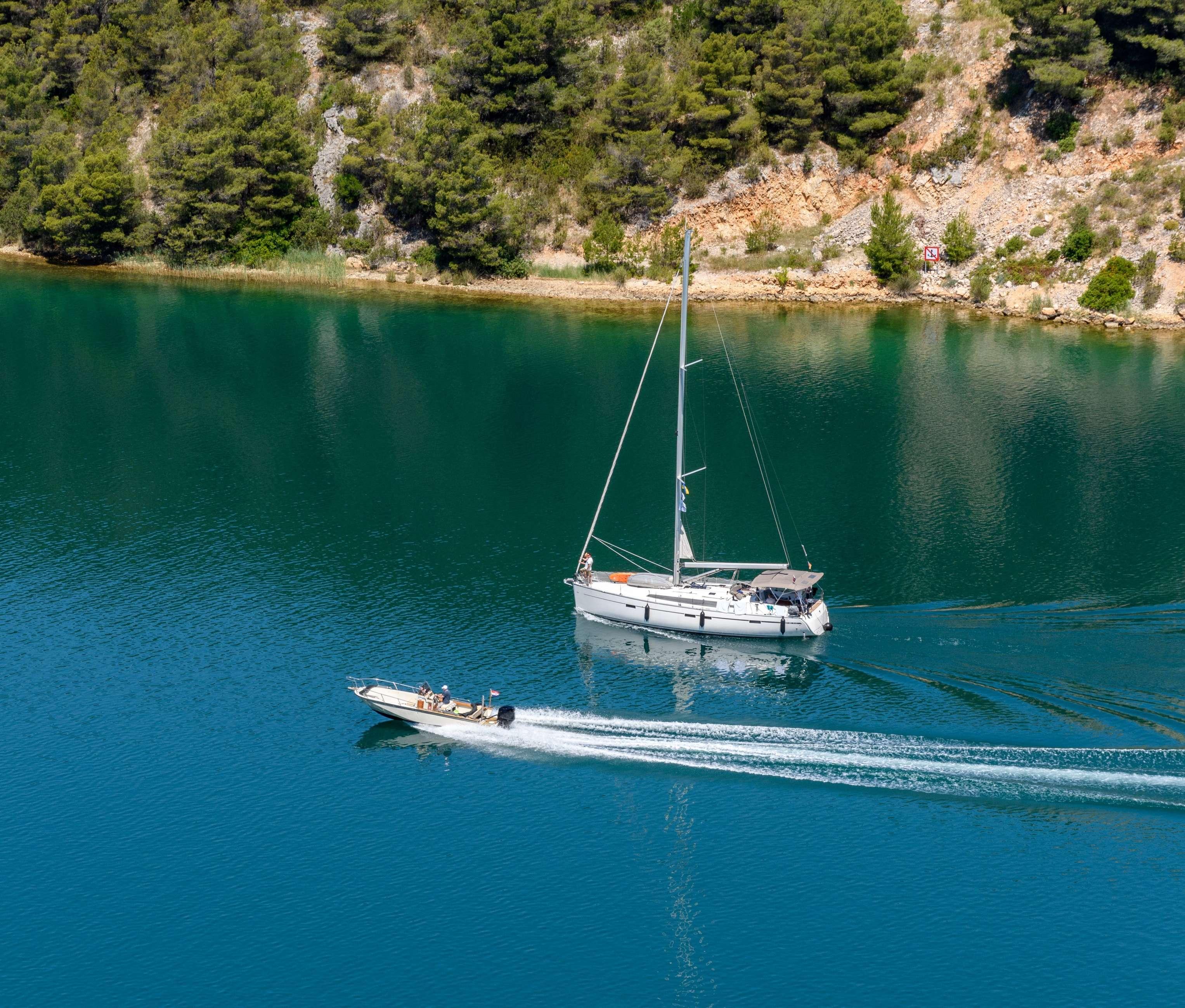
Sailboat or Motorboat – Learn the pros and cons lg ...
Aug 24, 2022
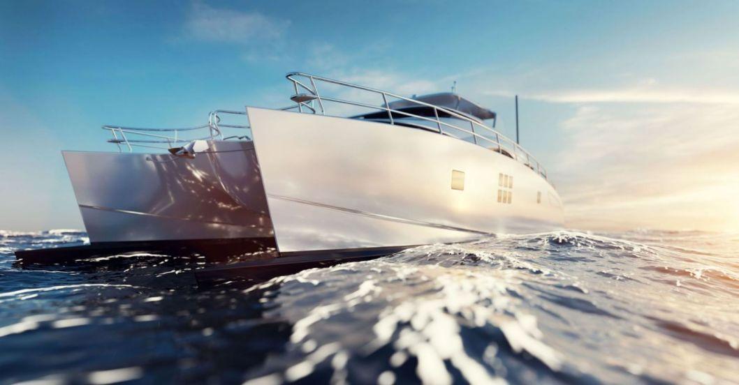
Types of Catamaran Boats: Sailing, Power, and Luxury Catamarans lg ...
Feb 10, 2023
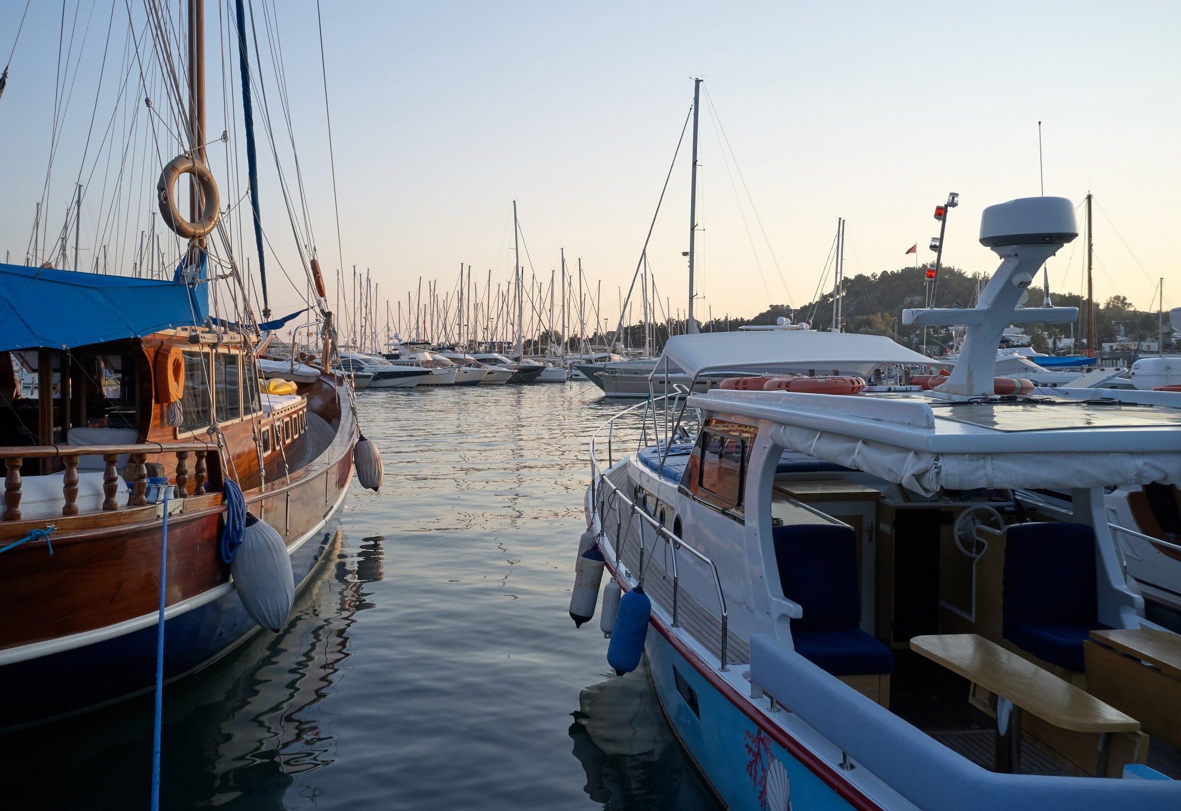
Which is better a wooden boat or fiberglass boat lg ...
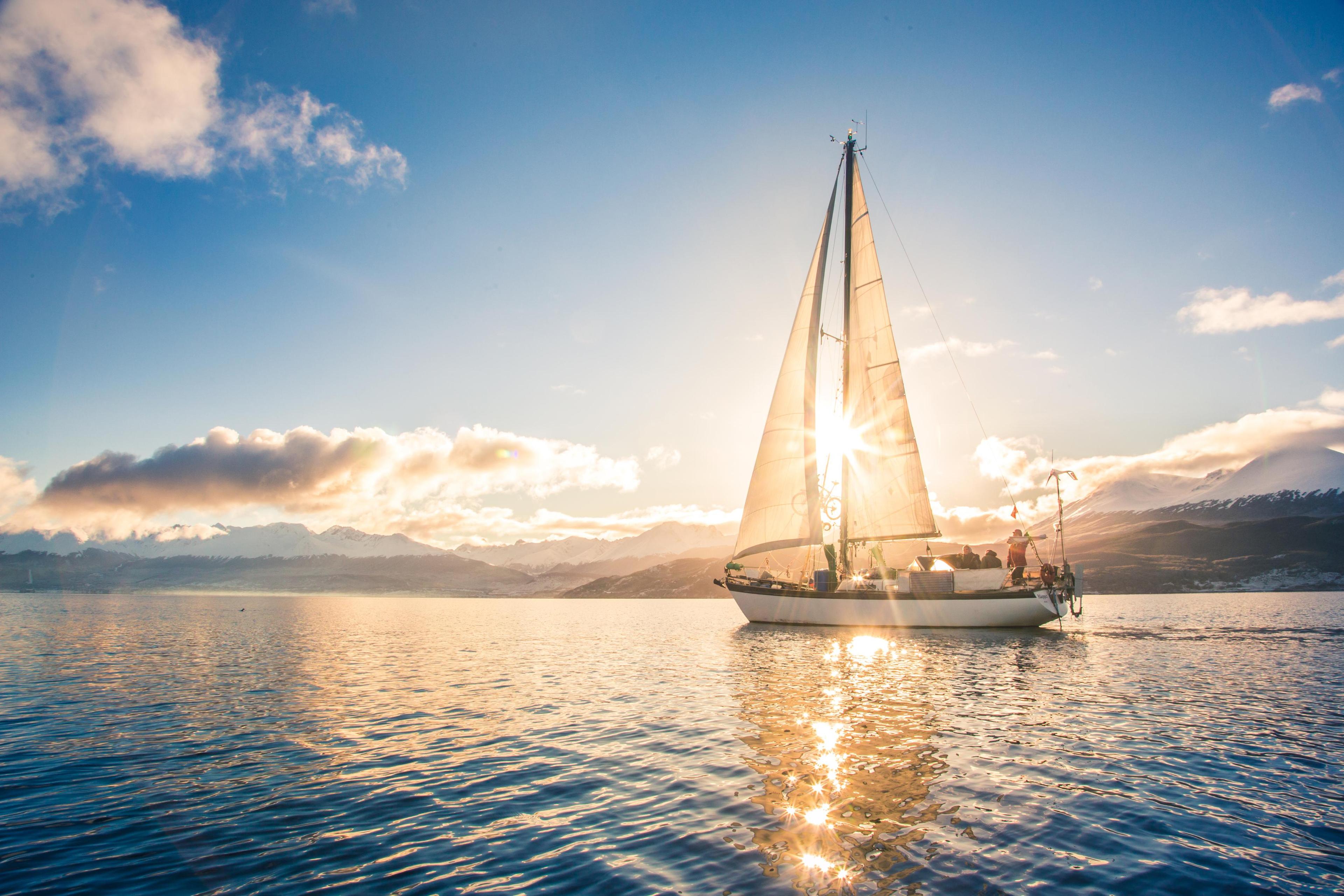
What are the main types of sail rigs for sailboats lg ...
Which is the Best Economical Catamaran lg ...
Oct 04, 2021
What is a Chine on a Boat lg ...
Oct 01, 2021
15 Surprising Facts About Modern Sailboat Design

February 28, 2024
Key Takeaways
- Modern sailboat design dramatically enhances performance and experience.
- Understanding these design changes adds depth to our appreciation of sailing.
- Innovations in design are influenced by changes in racing regulations.
Discover the surprising facts about modern boat design as we explore the leaps and bounds that modern sailboat design has made.
The surprising facts about modern boat design are the use of advanced materials, computer-aided designs, hydrodynamic hulls, wind tunnel testing, and articulated rudders. The modern boat design also incorporates wing sails, and twin rudders, among other innovative designs.
As a sailing enthusiast, I possess a deep understanding of the intricacies that shape the modern sailing world. My knowledge encompasses the latest advancements in hull design, rigging techniques, materials, and sustainability practices. As such, I’ll reveal surprising facts that shed light on the innovation and engineering excellence driving the evolution of sailboat design in the 21st century.
Table of contents
Surprising Facts About Modern Sailboat Design
Have you ever looked at a modern sailboat and wondered about the innovative marvels that distinguish these vessels from their ancestors? The world of sailing has transformed dramatically, thanks to cutting-edge technology and revolutionary design elements.
Let's dive into the surprising facts that make today's sailboats a tidal wave of innovation.
From materials that sound straight out of a sci-fi novel to rudders that think for themselves, these facts will give you a new perspective on sailboats.
1. Advanced Materials
Modern sailboat design has been revolutionized by the use of advanced materials like carbon fiber and Kevlar, which offer unparalleled strength-to-weight ratios.
These materials are not limited to the hull; they have also transformed masts and rigging, resulting in lighter, faster, and more durable vessels.
Sailboats can now harness the power of these cutting-edge materials to achieve remarkable performance while maintaining structural integrity.
2. Computer-Aided Design (CAD)
The introduction of Computer-Aided Design (CAD) technology has elevated sailboat design to new heights.
Engineers and designers can now meticulously craft and simulate sailboat designs before the first physical piece is ever built.
This precision-driven approach allows for the creation of sailboats tailored for optimum performance, ensuring that every element, from hull shape to sail configuration, is optimized to perfection.
3. Hydrodynamic Hulls
Modern sailboat hulls are meticulously designed with hydrodynamics in mind. These sleek, streamlined shapes minimize drag and maximize speed, marking a significant departure from the bulky hulls of the past.
Sailboats are now engineered to slice through the water with minimal resistance, enhancing their overall performance.
4. Wind Tunnel Testing
Wind tunnel testing, a practice well-known in many industries has also made its way into sailboat design.
Sailboats undergo rigorous wind tunnel testing to perfect sail shapes and rig setups, optimizing aerodynamic efficiency.
This meticulous approach ensures that every knot of speed is squeezed out, making sailboats faster and more competitive.
5. Hydrofoils
Hydrofoils are like the magic carpets of the sea, revolutionizing sailboat speed and performance.
As speed increases, these underwater wings lift the hull above the water's surface, drastically reducing drag. They also enable breakneck speeds that were once considered unattainable for sailboats.
6. Articulated Rudders
Articulated rudders represent a significant advancement in sailboat design , offering sailors a remarkable degree of maneuverability and precise control, particularly at high speeds.
Comparable to a race car driver fine-tuning their steering, skippers can now navigate sailboats with exceptional precision. These rudders respond swiftly to helm adjustments, enhancing safety and optimizing performance in various conditions.
Whether executing tight maneuvers or maintaining a steady course, articulated rudders empower sailors with unparalleled control, making them a game-changer in modern sailboat design.
7. Wing Sails
The adoption of wing sails in sailboat design marks a departure from traditional canvas sails and ushers in a new era of sailboat efficiency and adaptability.
Resembling the wings of an airplane, these sails offer sailboats increased power, precise control, and exceptional adjustability.
Sailors can harness the wind more efficiently, optimizing their sail configurations to suit changing conditions.
Wing sails respond rapidly to shifts in the wind, providing a level of adaptability that was once unimaginable. This innovation has transformed sailboats into highly responsive and versatile vessels, ensuring optimal performance on the open seas.
8. Sustainability Features
Sustainability is at the forefront of modern sailboat design, reflecting the growing commitment to eco-friendly practices within the sailing community.
Sailboats are now equipped with innovative features such as electric propulsion systems, solar panels, and advanced water purification systems.
These sustainable technologies reduce environmental impact, allowing sailors to cruise the open seas while minimizing their carbon footprint.
As sustainability takes precedence, the integration of these eco-friendly features not only aligns with environmental values but also enhances the overall cruising experience, making it more responsible and enjoyable.
9. Self-Tacking Jibs
The introduction of self-tacking jibs has streamlined sailboat maneuvering , particularly for solo sailors or small crews. These ingenious sails automatically adjust to the wind's direction, eliminating the need for manually grinding winches when changing course.
This innovation significantly enhances convenience and usability, making sailing more accessible to a broader range of enthusiasts.
Whether navigating through gusty winds or executing precise tacks, self-tacking jibs simplify the sailing experience, allowing sailors to focus on enjoying the journey without the hassle of constant sail adjustments.
10. Canting Keels
Canting keels represent a pivotal development in sailboat design, offering a solution to the age-old challenge of sailboat stability when heeled over. These keels can be shifted from side to side, counteracting the natural inclination of sailboats to capsize when tilted.
This innovation allows for a more aggressive sail plan, enabling sailboats to achieve higher speeds without compromising safety.
The canting keels' ability to maintain stability while heeled over has revolutionized sailboat racing and performance, pushing the boundaries of what sailboats can achieve on the water.
11. Twin Rudders
Two rudders mean better control, especially when heeling, and improved performance by maintaining steerage even in challenging conditions.
It's like having four-wheel steering in your car—a game-changer for sure.
12. Integrated Navigation Systems
Touchscreen displays, GPS, and autopilot systems are no longer just for luxury cars. They've found their way onto sailboats, providing sailors with all the navigational aids they need at their fingertips.
13. Resin-Infused Hulls
Resin-infused hulls represent a pivotal advancement in sailboat construction, delivering stronger, lighter, and more resilient vessels with a superior finish.
This innovative manufacturing process involves infusing resin into a precisely arranged fiber matrix, resulting in a structurally sound hull that is both lightweight and exceptionally durable.
The benefits are twofold: a faster sailboat due to reduced weight and increased resilience to the elements.
14. Sail-Material Innovations
Modern sailboats continue to push the boundaries of speed and performance, thanks in large part to sail-material innovations.
Sails are now crafted from laminated fabrics and exotic fibers that are not only capable of withstanding the punishment of the high seas but also offer enhanced performance.
These advanced materials provide superior durability and strength, allowing sails to maintain their shape and efficiency even in challenging conditions.
Sailors can confidently navigate rough waters, harnessing the full potential of the wind to achieve remarkable speeds.
These sail-material innovations are at the heart of modern sailboat design, enabling sailors to explore new horizons and set sail like never before.
15. Foil-Assisted Monohulls
Foil-assisted monohulls represent an exhilarating advancement in sailboat design, harnessing the power of underwater wings to provide additional lift.
This innovative feature effectively reduces drag and allows the sailboat to ride higher and quicker in the water.
The result is a thrilling sailing experience that combines speed, stability, and agility. Foil-assisted monohulls are a game-changer for sailors who seek the thrill of high-speed sailing while maintaining control and stability.
This technology has redefined what is possible in monohull sailboats, offering an exhilarating ride for sailors who crave speed and adventure on the open seas.
Impact of Racing Regulations and Rating Systems on Sailboat Design
The world of sailboats is more intricate than it seems, especially when you throw in racing regulations and rating systems.
Regulations and rating systems aren’t just red tape; they are the invisible architects of modern sailboat design. From tweaking hull shapes to adjusting ballasts, these rules stir the pot, leading to innovation in search of that extra knot of speed.
Here’s a simple breakdown highlighting how racing regulations and rating systems have dramatically influenced sailboat design:
Frequently Asked Questions
Here are the FAQs on modern sailboat designs.
Can you list some notable evolutions in sailboat design since their invention?
Absolutely! Over time, sailboats have shed some serious weight and bulk. Think less 'pirate galleons', and more 'sleek sea greyhounds'. The nifty evolution includes trimmed-down overhangs at the bow and stern, giving modern sailboats a longer waterline for a given length overall.
What are a few unexpected benefits of modern sailboat design on the efficiency and speed of sailing?
For starters, contemporary sailboats are shaping up to be the marathon runners of the sea – sleeker, lighter, and roomier. All that extra width isn't just for cocktail parties on deck; it's for stability.
How do modern sailboats incorporate sustainability and eco-friendliness into their designs?
Designers are harnessing materials and technologies that lower the environmental impact like inventive hull coatings to reduce drag and engines that sip rather than gulp fuel.
Jacob Collier
Born into a family of sailing enthusiasts, words like “ballast” and “jibing” were often a part of dinner conversations. These days Jacob sails a Hallberg-Rassy 44, having covered almost 6000 NM. While he’s made several voyages, his favorite one is the trip from California to Hawaii as it was his first fully independent voyage.
by this author
Trending Now

What Does "Sailing By The Lee" Mean?

Best Sailing Duffle Bags: Top Picks For Boat Travel

The Best Sailing Schools And Programs: Reviews & Ratings

Affordable Sailboats You Can Build at Home

Best Small Sailboat Ornaments

Best Small Sailboats With Standing Headroom

Discover the Magic of Hydrofoil Sailboats

Best Bluewater Sailboats Under $50K

Hunter Sailboats: Are They Built for Bluewater Cruising?

How To Buy A Cheap Sailboat

What Is A Furler On A Sailboat?

How To Choose The Right Sailing Instructor

What Is Sail Roach?

Best Blue Water Sailboats Under 40 Feet

What Is A DaySailer Sailboat?

Are Catalina Sailboats Bluewater Boats?

Best Sailing Racing Electronics

How To Sail From California To Tahiti

Best Sailing Destinations In BC

Best Sailing Charter Destinations

Which Sailboats Have Lead Keels?

Best 2 Person Sailboats

What Sailboats Are Made In The USA?

Best Sailing Racing Compasses

Which Sailboats Hold Their Value?

Can You Sail In Maine In October?

Most Reliable Sailboats

Common Issues With Amel Yacht Sailboats

Basics Of Sailboat Racing Explained

What Is The Steering Wheel On A Ship Called?

Everything You Can Pull Behind A Boat

How To Tow A Skier Behind A Boat

Most Popular One-Design Sailboats

How Long Is A Laser Sailboat?

What Sailboats Are Used In The Olympics?

Why Do Sailboats Lean?

Cost To Dock A Sailboat

Cost To Sail Around The World

How Often Do Sailboats Capsize & Sink?

Are Sailboats Bad For The Environment?

Best Marine Epoxy

Best Sailing Destinations Chesapeake Bay

Best Pontoon Boat Brands

Best Marine Refrigerators

Best LED Navigation Lights

Best Marine Air Conditioners

Best Boating Watches For The Avid Sailor

Are Sailboats Cheaper Than Powerboats?

How Much Does A Laser Sailboat Cost?

How Often Do Sailboats Get Struck By Lightning?

How Do Sailboats Float?

Best Marine Water Softeners

Best Sailing Shirts

Best First Aid Kits For Boat Safety

Why Do Catamarans Have Trampolines?

Best Ropes For Mooring Lines

Who Has To Wear A Life Jacket On A Boat?

How Old Do You Have To Be To Wear A Life Jacket On A Boat?

Where To Store Life Jackets On A Boat

Best Winter Pontoon Boat Covers

Bennington Pontoon Winter Cover Review

Best Pontoon Boat Cover Support Systems

How To Paint Pontoon Boat Fencing

What To Bring On Pontoon Boat

What To Wear On A Pontoon Boat

Pontoon Boat Winter Storage Ideas

Best Pontoon Boat Accessories

How Tall Is A Pontoon Boat On A Trailer?

Where To Attach Tow Ropes To Pontoon Boats

Best Trolling Motors For Pontoon Boats

Best Pontoon Boats For The Money

Best Pontoon Winter Storage Blocks

How To Launch A Pontoon Boat By Yourself

Best Pontoon Boats

How Much To Rent A Pontoon Boat? (Cost)

What To Avoid When Buying A Pontoon Boat

Best Grills For Pontoon Boats

How To Store A Pontoon Boat For Winter

SwellPro SplashDrone 4 Review (Is It Worth It?)

Best Anchors For Pontoon Boats

What Size Trolling Motor For 24ft Pontoon Boats?

How Many People Can Fit On A Pontoon Boat?

Best Small Pontoon Boats

How To Start A Pontoon Boat

How Fast Can Pontoon Boats Go?

What Size Motor For A 20ft Pontoon Boat?

Where To Put Numbers On A Pontoon Boat

How To Launch A Pontoon Boat

How Much Do Pontoon Boats Cost?

Best Fishing Pontoon Boats
How Wide Is A Pontoon Boat Trailer?

How To Store A Pontoon Boat Without A Trailer

Best Pontoon Boat Covers

Top 5 Pontoon Boats (Best Brands & Options)

How To Add Flags To Pontoon Boats
Who Makes Crest Pontoon Boats?

What Is Underpinning On A Pontoon Boat?

How To Drive A Pontoon Boat

How To Anchor A Pontoon Boat
How Wide Is A Pontoon Boat?
Get The Best Sailing Content
Top Rated Posts
Lifeofsailing.com is a participant in the Amazon Services LLC Associates Program, an affiliate advertising program designed to provide a means for sites to earn advertising fees by advertising and linking to Amazon. This site also participates in other affiliate programs and is compensated for referring traffic and business to these companies. (866) 342-SAIL
© 2024 Life of Sailing Email: [email protected] Address: 11816 Inwood Rd #3024 Dallas, TX 75244 Disclaimer Privacy Policy
Boat Parameters
Here is a list of definitions for the various parameters used to describe boats.
As a general rule, parameters and ratios listed on the M. B. Marsh Design site are for the boat at its fully loaded design displacement, including full tanks, full crew, and typical cargo. The one exception is the light-ship displacement figure, which is (roughly) the weight of the fully fitted out, but unloaded, boat as it leaves the construction shed.
For multihulls, most of these parameters (with the exception of waterline beam) apply to the boat as a whole. In the case of trimarans and proas, waterline beam and length are stated separately for the outriggers, and wetted surface includes as much of the boat as would be in the water in normal operating conditions.
If you'd like to read more on where these parameters come from, a good place to start is Eric Sponberg's article "The Design Ratios", which can be found at http://www.sponbergyachtdesign.com/Articles.htm .
Topic:
- Boat Design
Displacement
Definitions.
Displacement is the truest measure of just how much boat you're dealing with. In a nutshell, it's the actual volume or weight of the vessel.
Of course, there are more than a few ways to state displacement, but only two- the volume displacement and the displacement mass, both at the design waterline- are fair points of comparison between different boats. The rest, although important and helpful when used properly, can be deceptive when seen alone. Always ask which weight is really being discussed, and what's included in it!
Units: Volume measure (cubic metres or cubic feet) for volume displacement, or mass (kilograms/tonnes or pounds/long tons) for the others.
Volume displacement ($\nabla$ or D)
The total volume of water displaced by the boat when she's sitting on her design waterline. Or, equivalently, the below-waterline volume of the hull and appendages.
Displacement at design load, or displacement mass (m LDC )
The weight of the boat when she's loaded to her design waterline. By Archimedes' principle, displacement mass is equal to displacement volume multiplied by the density of the water (nominally 1000 kg/m 3 or 62.4 lb/ft 3 for fresh water, 1025 kg/m 3 or 64 lb/ft 3 for seawater). This is the figure that should be used for all performance ratios and comparisons.
Displacement light-ship, or empty boat displacement mass, or dry weight (m LCC )
The weight of the boat when she leaves the build shed, before there's any personal gear brought aboard and before any fuel or water are put in the tanks.
Although it's important to determine m LCC when designing and building a boat, it'll never be sailed this light. Performance ratios calculated using the dry weight are worse than useless; nevertheless, some marketing materials list only this weight and numbers based on it in an attempt to trick the buyer into thinking the boat is faster and sportier than it really is.
Light load displacement mass (m MOC )
The weight of the boat with (usually) half-full tanks, a standard complement of essential gear, and a small crew. This is the absolute lightest weight the boat is ever likely to be sailed at, and performance ratios based on m MOC can be deceptively racy.
There appear to be no less than six commonly used ways to measure the length of a boat. Most of the discrepancies have to do with whether stern platforms and bow pulpits are "integral parts of the hull" or are bolted on separately.
Units: Linear measure (usually metres/centimetres or feet/inches).
Length overall (L OA )
The length from the forward tip of the stem to the aftmost point on the hull. Usually includes any bow or stern appendages that are a structurally integral part of the hull (eg. a swim platform or anchor pulpit moulded as part of the hull), but excludes bowsprits, boomkins, bolted-on pulpits and stern platforms, or other appendages that aren't an integral part of the hull itself.
Length waterline (L WL )
The length of the design waterline, i.e. the length of the part of the boat that's in the water when she's loaded exactly to the waterline shown on the plans.
Length between perpendiculars (L PP )
The length from the forward point of the design waterline (same as for L WL ) to the centre of the rudder stock. Used mainly for large ships, and rarely mentioned aboard anything under a hundred feet or so.
Length on deck (L D , L OD )
The length from the foremost point of the deck to the aftmost point of the deck; it leaves out reverse-sloping transoms and most types of integral pulpits.
Length of hull (L H )
The overall length of the hull itself. Defined similarly to L OA , but usually excluding bow pulpits.
Rated length
Depends on which rating rule your boat is subject to. This is usually some combination of LOA, LWL and various parameters describing the shape of the bow and stern overhangs.
Which one to use?
For marina fee purposes (they're measuring).
Marina administrators often like to use the total length of the boat, including bowsprits, boomkins, pulpits, protruding sterndrives, the trailer tongue, and other length-extenders that would be considered "cheating" if you used them to describe your boat to a friend. That 18-foot runabout? 22'6" to the boatyard, once you add the tilted-up outboard and the trailer tongue.
For marina fee purposes (you're measuring)
If you're being billed by length, you'll try to low-ball the measurement. For a powerboat, L PP is usually the shortest, so you might start there. That might seem suspicious, though, so L WL and L H are the next to be presented. Eventually, you and the marina manager will grudgingly agree to use L OA , at which point a long and drawn-out argument will ensue over whether that anchor pulpit really is "integral to the hull".
In a builder's marketing brochure (model number, etc.)
It could be any of a number of quantities of questionable origin. Popular ones include "Take L OA in feet, round up, append two random digits". Or "Take L OA in feet, add swim platform but not anchor pulpit, round to nearest inch, state as FtIn". Or, "Take L OD in dekametres, add pulpit but not swim platform, round to nearest multiple of five".
At Marsh Design, the model number is the L OA in centimetres, using the standard definition given above.
When comparing performance
That would be L WL . For speed and seakeeping, you care about how much boat is actually in the water. That is, after all, what the waves see, and it's the length used to compare Froude number or speed/length ratio.
Beam refers to the width of a boat. As with length, there are a few ways to define beam, depending on what you need the number for.
Beam overall (B OA )
The maximum width of the boat, excluding rub rails or lifeline stanchions that may protrude past the edge of the hull.
Beam waterline (B WL )
The width of the waterplane when the boat is loaded to the design waterline shown on the plans. On multihulls, B WL refers to the waterplane width of a single hull.
Beam centreline (B CB , B CL )
For multihulls only, the lateral spacing between hulls.
For most purposes
Beam overall is the most commonly used description of a boat's width. It gives some indication of how spacious the interior will be, and how wide a slip needs to be to accommodate the boat. B OA , plus a comfortable margin, is the dimension used when determining whether the boat can pass through a canal or fit in a slip.
When comparing sailboat performance
For monohulls, B WL is the quantity of interest. Wider beam implies greater form stability, within a given family of hulls. All other things being equal, the hull with more form stability will be less tender and better able to stand up to a powerful sail plan. Making a hull wider, though, will generally increase wave-making resistance, and often increases wetted surface area- thus increasing frictional resistance. Finding the right trade-off is one of those "no right answer" optimization problems that make good design tricky.
Multihull performance depends on both B WL and B CL . The former contributes to the resistance; the latter contributes to the multihull's righting moment and therefore its sail-carrying power.
The effect of beam on performance is better understood by looking at the length/beam and beam/draught ratios.
When comparing powerboat performance
B WL is, once again, the appropriate quantity to compare. Since a powerboat doesn't need to stand up to a full press of sail, initial stability (due mainly to form stability, or hull shape) is more a matter of preference- although there are long-standing guidelines for what works well in a given situation.
If a hull is capable of planing, B WL becomes a very important factor. A wider running surface gives more planing lift, but also presents more area for the hull to pound on when bashing through waves.
Draught, normal (T)
The depth of water needed to float the boat, when it's loaded to its design displacement and sitting on its design waterline.
Draught, minimum (T min )
In a boat with retractable appendages (rudder, daggerboards, outboard or sterndrive engine), the depth needed to float the boat when all these appendages are fully retracted. Again, this measurement is based on the design waterline.
Most of the time, the maximum (normal) draught, plus a comfortable margin, is the figure of interest. T min is relevant only for a handful of boat types, and then only in those specific conditions when you can safely run with the keel, rudders or engine retracted. Very few retractable keel monohulls, for example, can be sailed with the keel up (although many centreboard boats can run downwind with the board retracted).
Wetted surface area
Wetted surface area is the total surface area of the hull and appendages below the waterline. It should include both sides of the rudder and keel, and if the boat has multiple daggerboards, the given wetted surface area usually includes as many foils as would be used simultaneously.
Units: Area (usually square metres or square feet).
What it's used for
Performance.
Any surface that's in contact with the water causes drag; frictional resistance depends on how much surface area is in contact with the water. Less wetted surface area generally means less frictional drag.
In a sailboat, frictional drag usually dominates at low speeds, so minimal wetted surface is important to light-air performance. (This is better understood in terms of the ratio of sail area to wetted surface.)
In faster powerboats, and even some sailboats, the hull will climb on plane as it accelerates. Once on plane, wave-making resistance drops off dramatically, while frictional resistance increases. Wetted surface is once again an important factor, but since part of the hull is now out of the water, it's not the same wetted surface as in the at-rest condition!
Maintenance
Wetted surface area is, not coincidentally, the area that needs to be covered by antifouling paint. It's therefore a useful quantity to know when figuring out how long it will take, and how much it will cost, to paint the boat.
Length-beam ratio
L/B = length divided by beam.
Units: Dimensionless.
Usually, the waterline dimensions L WL and B WL are used for monohulls, or for a single hull of a multihull.
Larger L/B indicates a slimmer hull. This usually implies less wave-making resistance, and thus more efficient high-speed performance, but also suggests reduced load-carrying ability for a given length.
If a boat can plane, smaller L/B often suggests more efficient performance at low planing speeds. The balance generally tilts in favour of high L/B for fast boats.
Typical ranges of L/B are:
2 to 4 - Small to mid-size planing powerboats.
3 to 4 - Most small to mid-size sailboats and motor yachts, the longer ones generally having higher L/B. Some "skimming dish" racing sailboats also have L/B in this range; their wide beam gives them more initial stability so that they can fly larger sails.
4 to 6 - Fairly long and lean for a monohull. Some large, efficient long-range cruisers fall in this range, along with many racing monohulls.
6 to 10 - Large freighters; main hulls of cruising trimarans; a few very portly cruising catamarans; the lightest and slimmest of large sailing monohulls.
10 to 16 - Fast cruising cats and tris; a few racing multihulls.
Over 16 - Racing multihulls. Such high L/B is conducive to very light, low-drag hulls for race boats, but makes it very hard to get enough room inside the hulls for equipment or living space.
Living Space
If a boat is going to spend most of its time in a marina or at anchor, relatively low L/B implies a larger, more spacious interior and increased carrying capacity when compared to slimmer competitors of the same length. For a boat that must entertain guests at the dock but will rarely be used in rough weather or at high speeds, this may be a significant advantage. The slimmer boat, though, will generally have the advantage when fuel is expensive or when the weather picks up.
Bottom loading
Bottom loading is the displacement mass divided by the area of the planing surface (usually somewhat less than the total wetted surface ).
Since the area of the planing surface constantly varies, it's common to just use B WL * L WL as the reference area.
Units: Usually kilograms per square metre, or pounds per square foot. One might think of bottom loading in terms of pressure, but that can lead to confusion- so I prefer to avoid using units of pressure (Pa, or N/m 2 ) to describe bottom loading. Just think of it as another arbitrary ratio that can be used to compare boats.
Planing performance
Bottom loading is a very useful figure when trying to determine how well a hull will plane. Higher bottom loading indicates that more lift must be produced by a given size of planing surface, so the boat will have to run faster or at a steeper trim angle to get on plane. We must confirm, of course, that the hull shape is amenable to planing- straight buttocks, roughly prismatic afterbody, etc.- before this ratio will be of much use.
In general, lower is better, within reason. A boat whose bottom loading is much less than her competitors' will be quicker to pop onto plane and better at low to moderate speeds, but may have a bouncy ride in rough weather.
Less than 100 kg/m 2 (20 lb/ft 2 ) - This implies a very light hull that should pop up on plane quickly at low speeds.
About 200 kg/m 2 (40 lb/ft 2 )- For boats in the 4 to 7 metre range, this is the point where getting up on plane needs a bit of effort, and there may be a range of "no-go" speeds where the boat plows around with its bow in the air. Once up, planing can be easily sustained.
About 300 kg/m 2 (60 lb/ft 2 )- For a boat in the 4 to 7 metre range, overloading is indicated, and the boat probably won't plane very well. Given enough power, it may run OK at high speed, but will be a dog from 8 to 20 knots or so. In boats from 10 to 15 m L OA , bottom loadings in this range are typical and indicate reasonable performance.
About 400 kg/m 2 (80 lb/ft 2 )- Bottom loadings in this range on a 5 to 10 m boat indicate almost no ability to plane. On a 10 to 15 m boat, this bottom loading would indicate slight overloading and poor low-to-moderate speed performance, and on a 20 m boat would imply typical, but unremarkable, planing performance.
Yacht Design: Design Links/Articles
- Any questions
- Historic Boat Design
- Marine Industry News
- Marine Systems
- Using EBSCO Folders
- EBSCO Tutorials
- EBSCO Alerts
- Books - Online
- Finding Articles
- Terminology
- Basic Sailing
- Sailing Yacht hull forms
Articles on Boat Design
- Design Ratios by Eric Sponberg A primer on some basic principles of naval architecture for small craft. (from the site)
- Motion Comfort Ratio A brief article on Brewer's motion/comfort ratio.
- Keel and Rudder Design Summary of a lecture presented at an IBEX conference by Davide Vacanti, Eric Sponberg, and Kevin Milne in 2004.
- Design Basics The following ratios and factors are commonly used by naval architects and boat designers to help them predict how a specific design will perform. The selected values represent those found on a typical offshore cruising boat, where safety and comfort are of primary importance. (from the site)
- Naval Architect's Notebook Modern sailboat design requires a certain amount of engineering and naval architecture calculations. Here are a few files (more will be added) to serve as an example of some of the number crunching and computer modeling that is part of the sailboat design process. (from the site) Paul R. Kotzebue, PE Mechanical Engineer
- Sailboat Design Ratios This page attempts to provide explanations for the basic sailboat design ratios used to compare boats with one another. Some of it is my interpretation of what I have read in the books, articles, and web pages I refer to below. I do not claim to know anything about these subjects so, as with anything you read on the internet, it's up to you to evaluate it's worth. (Dan Pfeiffer)
- Pro boat on capsizing
- Pro Boat on slamming loads
- Designing consoles for speed {PBB}
- Power & Speed predition for fast power boats Michael Peters article in pro Boat
- proboat on Eng -Rm arrangement fitting in the major items
- BoatDesign.net This site "connects boat builders and designers on the web, highlighting innovations in both small and large sailboat and powerboat design, showcasing great boatbuilding projects by amateurs and professionals, and providing access to resources, materials, and inspirational sites." (from the site)
- Boat Hull Designs This article by Alex Zidock Jr was featured in the July/August 1999 issue of Angler & Boater.
- Free Boat Design Resource Design Software Description and links to various software packages that are available free of charge through shareware license.
- Free Boat Design Resources This page was assembled by Gavin Atkin. I have a policy of concentrating mainly on material likely to be of interest to the low-budget sailor. (from the site)
- Keelboat Course Design and Safety U.S. Sailing site provides explanations of various sailboat ratios.
- Pilot Boats Part 1 This is a 2014 article from professional boatbuilder magazine
- Ted Brewer Presents a Primer on Yacht Design The Numbers (More Than You Ever Wanted To Know!) (from the site)
- Pilot boat part 2 Article from professional boatbuilder magazine
Talk the talk ...
Aspect Ratio : The ratio of span^2 to projected area for any lifting surface. This reduces to span/mean chord for trapezoidal planforms.
Bi Plane Rig : Two masts, arranged side by side, the same distance from the bow
Capsize : The boat has rolled 180 degrees to a stable, but upside down, condition
Catboat rig : A single mast, well forward, supporting one large mainsail.
CE : The Center of Effort is the centroid of a sail or sails.
CG :the center of gravity is the point where the mass or weight of a boat acts
Cutter :A single mast rig with two headsails. The second jib (stay sail) is often self tending and easy to use in strong winds.
Data Base : A tool for organizing information in three or more dimensions
Displacement : The weight of the boat as measured on dry land
Graphs :A method for visualizing information with two or, rarely, three dimensions, x = horizontal, y = vertical
Knots :Velocity, at a speed of one knot, a boat will travel one nautical mile in one hour
LOA : Length overall
Moment : The product of a force times a distance. Moments try to rotate things.
Overturning Moment : The product of the wind force times the center of effort
Pitch :rotary motion around the transverse lines ( the bow goes up and down when pitching)
Roll : rotary motion around the fore and aft lines. Sometimes called heeling
Spread : The difference in Y-axis data when the X-axis is held constant
Stable : In balance
Windward : The side facing into the wind
Yaw : rotary motion around the vertical axis ( the bow swings side to side )
- << Previous: Any questions
- Next: Rhino 3D >>
- Last Updated: Feb 2, 2024 2:58 PM
- URL: https://libguides.landingschool.edu/design
- Types of Sailboats
- Parts of a Sailboat
- Cruising Boats
- Small Sailboats
- Design Basics
- Sailboats under 30'
- Sailboats 30'-35
- Sailboats 35'-40'
- Sailboats 40'-45'
- Sailboats 45'-50'
- Sailboats 50'-55'
- Sailboats over 55'
- Masts & Spars
- Knots, Bends & Hitches
- The 12v Energy Equation
- Electronics & Instrumentation
- Build Your Own Boat
- Buying a Used Boat
- Choosing Accessories
- Living on a Boat
- Cruising Offshore
- Sailing in the Caribbean
- Anchoring Skills
- Sailing Authors & Their Writings
- Mary's Journal
- Nautical Terms
- Cruising Sailboats for Sale
- List your Boat for Sale Here!
- Used Sailing Equipment for Sale
- Sell Your Unwanted Gear
- Sailing eBooks: Download them here!
- Your Sailboats
- Your Sailing Stories
- Your Fishing Stories
- Advertising
- What's New?
- Chartering a Sailboat
Download Our Sailing eBooks Here!
All of our eBooks are in PDF format, which means you can download them straight to your inbox and read them on your phone, tablet, laptop and PC!

(but see our offer below before buying...)
How to Avoid Buying the Wrong Sailboat
Just how do you go about choosing a cruising sailboat from all the different designs and variations on offer?
Unless you apply some logical process to it, it's all too easy to end up with the wrong boat.
Allowing your heart to rule your head with these beguiling machines can lead to a deal of disappointment.
Wouldn't it be great to have a practical, no-nonsense approach which would avoid the many pitfalls?
Well, there is now - and it's a completely new way of going about it.
more info...

First Time Atlantic Crossing
The day-by-day account of a cruising couple's first Atlantic crossing.
If you're thinking about making a long, ocean passage with your dearly beloved, then Mary Swift's ebook 'First Time Atlantic Crossing' is a must-read.
Incidentally, Mary Swift is now Mary McClary...

(but see our offer below before buying...)
Interactive Sailboat Design Ratio Calculator
Calculate the 5 most important Design Ratios for any sailboat with our popular 'Cheat Sheet' !
The ' Interactive Sailboat Design Ratio Calculator' comes with the eBooklet 'Understanding Design Ratios' which will help you make sense of the numbers.

Secrets of Sailboat Fishing
Never go fishless again!
“Fishing from a sailboat? Waste of time. Dragged the darn lure for hundreds of miles and never had a sniff of a bite. Must have added a day to the passage!”
"All we wanted was a couple of mackerel for dinner, but we ended up with canned tuna again..."
Sounds familiar? Then my ebook 'Secrets of Sailboat Fishing' is for you.
more info.. .

Secrets of Buying Secondhand Boats
Spot those flaws and defects and get the best possible deal!
This ebook will provide you with the insight to more thoroughly inspect a used sailboat, together with the tips and techniques to close the deal should you decide to proceed.
The author, Andrew Simpson, is a professional marine surveyor, a yacht designer and boat builder with over 40 years of experience.
He's also a highly regarded yachting journalist and an offshore sailor with tens of thousands of sea miles under his keel.

Secrets of Windvane Self-Steering
Understand these wonderful devices and get the one that suits your boat best.
"Just how do wind vane systems keep the boat on course?"
"I know there are different types of windvane self-steering systems available but how do they compare?"
"Does the size of my boat have any bearing on the vane gear I should choose?"
"My boat has a centre cockpit. Is there a vane gear design that's compatible with this type of layout?"
"My boat's got wheel steering. Does this rule out a windvane self-steering system?"
All good questions! The answers to which are set out - in detail - in this ebook.
A Special Offer for Boat Buyers!
Bought individually, these 3 eBooks would cost you a total of $19.97, but bought together you can save 34%!
Special Bundle Price just $12.99!

Recent Articles
Wauquiez Gladiateur 33 for Sale
Apr 10, 24 05:40 AM
'Cabo Frio', a Catalina Morgan 43 for sale
Apr 01, 24 08:35 AM
Live Aboard Boats For Sale
Mar 30, 24 07:02 PM
Copyright © 2024 Dick McClary Sailboat-Cruising.com
IMAGES
VIDEO
COMMENTS
Our 'Sailboat Design Ratio Calculator' takes all the hard work out of calculating the numbers andwill provide a valuable insight into a sailboat's performance and handling characteristics. We make a small charge of $4.99 for this useful tool as a contribution towards the costs of keeping this website afloat. ThisSailboat Design Ratio Calculator ...
However, with the help of design ratios, you can not only compare and contrast different designs, but get a pretty good idea, sight unseen, as to how a boat is going to perform under sail. The Beneteau Sense 46 is a typical modern cruising boat, with an SA/D of 19, a Ballast Ratio of 28 percent and a D/L of 159.
The Design Ratios Sponberg Yacht Design Inc. 3 PREFACE In January 2010, a gentleman in Austria ("Capt. Vimes") visiting the Internet forum BoatDesign.net asked a question about the Center of Flotation and its implications on boat design and performance. I happened to be the first responder to the question, and
The first is the displacement to length ratio. The formula to calculate it is D / (0.01L)^3, where D is displacement in tons and L is waterline length in feet. But most sailboat specifications, like those found on sailboatdata.com, list the D/L Ratio. This ratio helps understand how heavy a boat is for its length.
Design ratios tell a story, but to get the real picture about a vessel, sail area, displacement, and ballast deserve a longer look. ... After the IOR fell out of favor, cruising-boat design drifted away from raceboat design, and sail plans began to change. Today, many boats are designed with large mainsails and small jibs, and most builders ...
crew) ratio. These are perhaps the extremes of sailboat design. Let's explore the middle ground, where most boats reside. Table 1 lists the key criteria for the design of keels for racers and cruiser/racers. Simple Planform Keels The "simple" or "standard" keels such as the one shown in Figure 1 would include high-aspect-ratio keels
Its stability ratio is thus 6.2: 196.56 ÷ 31.68 = 6.2. As a general rule, a stability ratio of at least 3 is considered adequate for coastal cruising boats; 4 or greater is considered adequate for a bluewater boat. The boat in our example has a very healthy ratio, though some boats exhibit ratios as high as 10 or greater.
Hull Design Ratios. The next group of numbers can only be provided by the designer (or by your own detailed analysis of the lines). ... During the design of a boat, the CG can only be derived by a rigorous weight analysis, including knowing the boat's structure, the structural weights, and the weights and centers of gravity of every item on the ...
After a 30 year absence, a veteran marine journalist returns to the US Sailboat Show and discovers the many changes in cruising boat design and construction. By Dan Spurr. Updated: June 10, 2020. The X-Yachts 46 displays the wide beam, twin wheels and open transom that define many 2020 models. Jon Whittle.
A boats design dimensions and a few simple ratios give some hints about these attributes. Most performance-oriented boat designs focus on around-the-buoy racing; these assume that there will be a large crew to keep sail area and trim optimized and to provide movable ballast and that the boat must cope with windward and leeward legs of a race ...
Empacher, Dieter (1997) By the numbers: The significance of design ratios in describing vessel performance, Ocean Navigator, 85: 64-66; Gerr David (2004) Stable by Design, Sail, September 2004, Vol 35 #9:68-73; Marshall, Roger (2000) Shaping an Offshore Hull, Ocean Navigator, 107: 56-63. Web Sites. US Navy Web-based Naval Architecture
Sailboat Design Definitions. Design definitions quoted from Pearson's own Bill Shaw are included here along with references to other performance and design documents for your perusal. "We asked Bill Shaw to list some of the basic design measurements and ratios that are used by the designers to define the performance characteristics of various ...
Ratios. Below are explanations of the various terms and coefficients used for comparison of boat designs. Designers use them when comparing designs from their own drawing boards and those of other designers. The same info can be used by the layman to assist in selecting a design to build. (from the site)
The number you get is then multiplied by 100. A ballast ratio more than 40 will be more powerful and more resistant to wind. A good ballast ratio however will mean that the boat might not be as comfortable for leisure. A very high ballast ratio is probably a better parameter for sport fans. These are the three main sailboat ratios to consider ...
Modern sailboat design has been revolutionized by the use of advanced materials like carbon fiber and Kevlar, which offer unparalleled strength-to-weight ratios. These materials are not limited to the hull; they have also transformed masts and rigging, resulting in lighter, faster, and more durable vessels.
Boat Parameters. Here is a list of definitions for the various parameters used to describe boats. As a general rule, parameters and ratios listed on the M. B. Marsh Design site are for the boat at its fully loaded design displacement, including full tanks, full crew, and typical cargo. The one exception is the light-ship displacement figure ...
For example, for displacement yachts sailing at their maximum speed/length ratio of 1.34, the optimum Cp is around 0.63. For semi-displacement yachts sailing at speed/length ratios between 0.6 and 1.1, the optimum Cp ranges from 0.63 to 0.68. For planing yachts sailing at speed/length ratios above 1.1, the optimum Cp ranges from 0.68 to 0.76.
A tool to calculate performance ratios for monohull sailboats. Use the search bar to look up dimensions for boats currently in our database. You may also enter a boat's dimensions directly in Part 2. Part 1: Search Database. Search. Search Results.
Aspect Ratio: The ratio of span^2 to projected area for any lifting surface.This reduces to span/mean chord for trapezoidal planforms. Bi Plane Rig: Two masts, arranged side by side, the same distance from the bow. Capsize: The boat has rolled 180 degrees to a stable, but upside down, condition. Catboat rig: A single mast, well forward, supporting one large mainsail.
Sailboat Design Ratios. See the excellent tutorial from Ted Brewer: Ted Brewer Presents A Primer on Yacht Design The Numbers (More Than You Ever Wanted To Know!) at: ...
Interactive Sailboat Design Ratio Calculator. Calculate the 5 most important Design Ratios for any sailboat with our popular 'Cheat Sheet'! The 'Interactive Sailboat Design Ratio Calculator' comes with the eBooklet 'Understanding Design Ratios' which will help you make sense of the numbers. more info...